Flow rate control using mass flow rate control device

Active Publication Date: 2010-01-07
HITACHI METALS LTD
View PDF21 Cites 239 Cited by
  • Summary
  • Abstract
  • Description
  • Claims
  • Application Information

AI Technical Summary

Benefits of technology

[0072]According to this aspect, it will be possible to generate second characteristic data that minimizes the effects o

Problems solved by technology

For this reason, if mass flow rate controllers that have been adjusted using nitrogen gas as the calibration gas are used without further adjustment in a semiconductor production system at the shipping destination, the problem of inability to achieve linearity with the same accuracy as with nitrogen gas may arise.
However, actual flows of actual process gases (hereinafter sometimes called “actual gases”) in the semiconductor production system at the shipping destination may give rise to discrepancies for which such conversion factors may not be able to fully compensate.
Also, in the case of a wide full scale flo

Method used


Image

  • Flow rate control using mass flow rate control device
  • Flow rate control using mass flow rate control device
  • Flow rate control using mass flow rate control device

Examples


modified embodiment 1

E1. Modified Embodiment 1

[0203]In the preceding modes of embodiment, the controlled flow rate correction data DPc is generated by a personal computer on the basis of the calibration gas characteristic data DPm and the actual gas characteristic data DPg. However, in another possible mode, the mass flow rate control device MFC0 can be provided as a constituent element with a processing module for generating the controlled flow rate correction data DPc.

modified embodiment 2

E2. Modified Embodiment 2

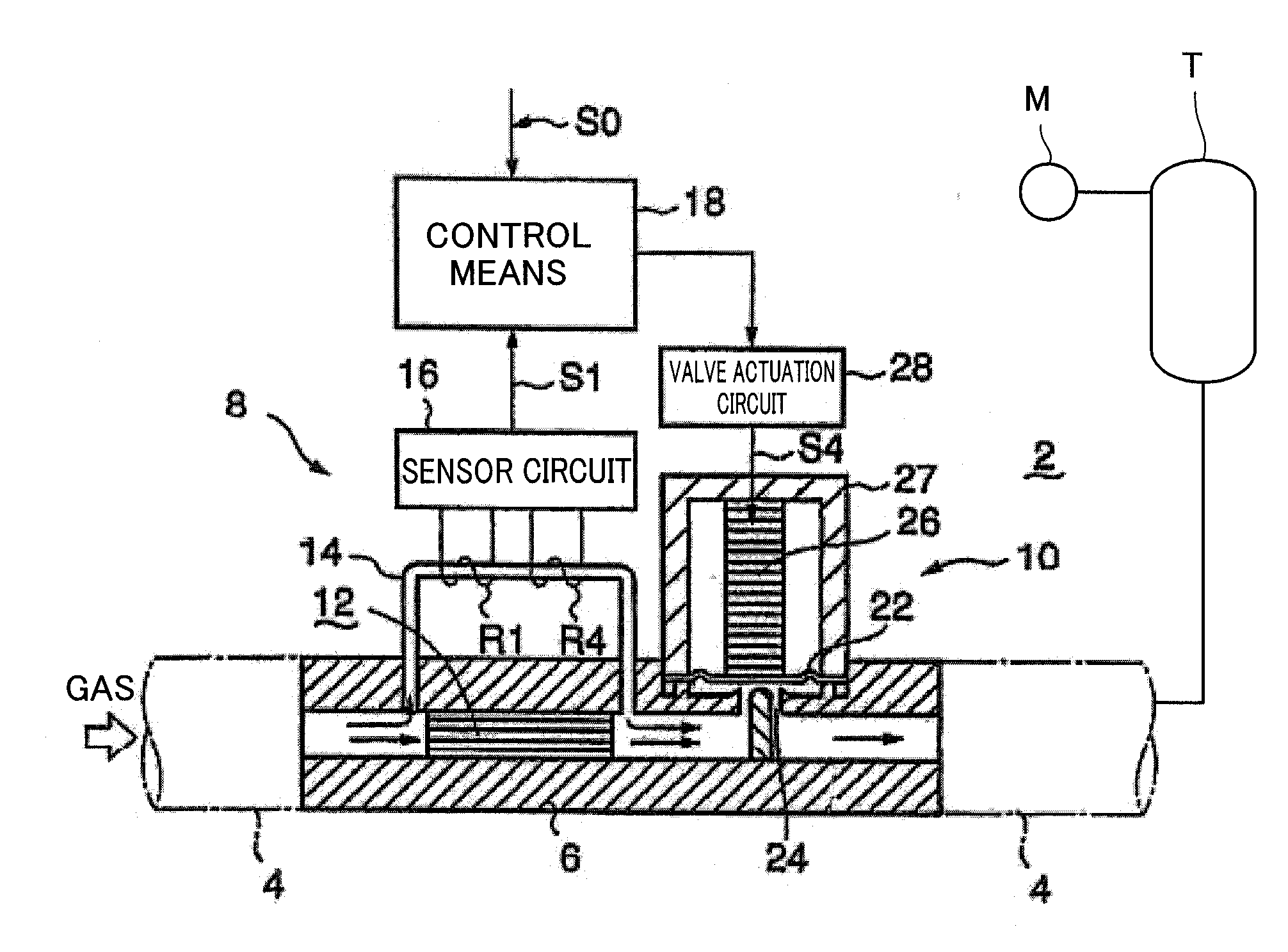
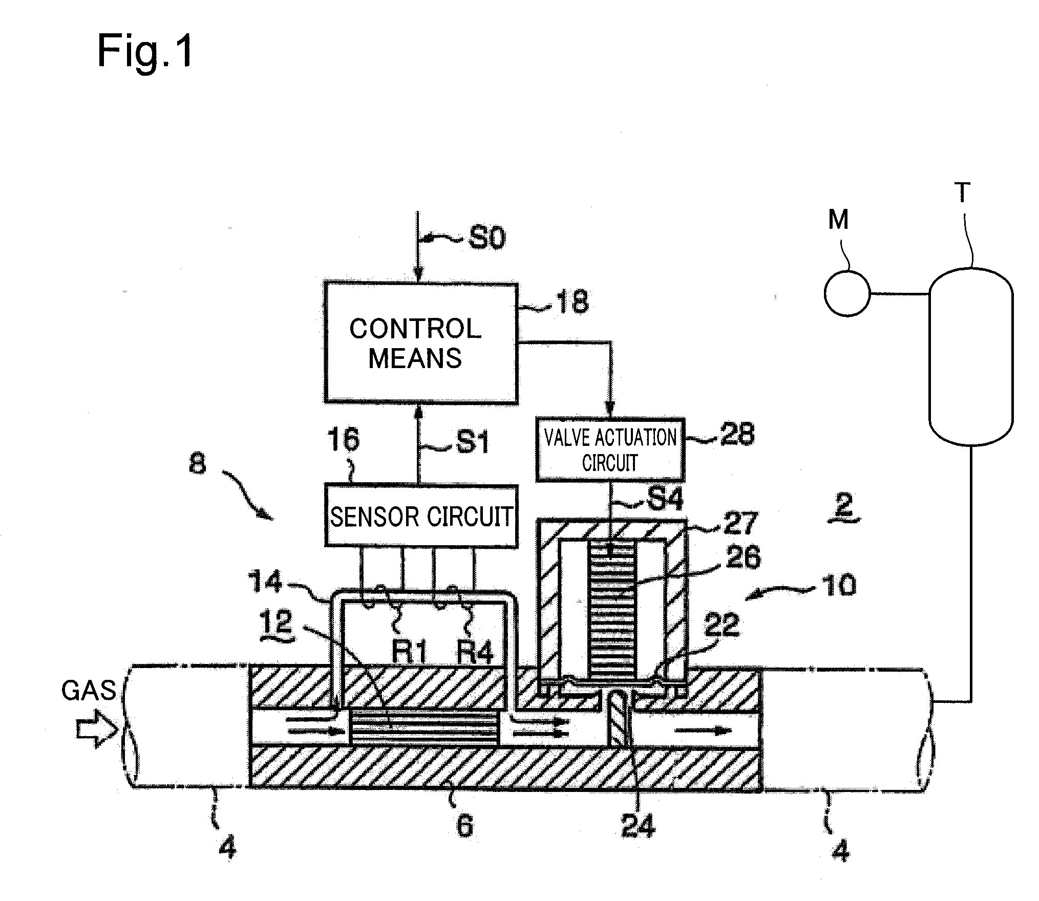
[0204]In the preceding embodiment, the device for measuring flow rate in the fluid passage 4 during generation of calibration gas characteristic data DPm and actual gas characteristic data DPg is a device furnished externally to the mass flow rate control device MFC0. One example of such a flow rate measuring device is a tank connected downstream from the mass flow rate control device MFC0, the tank being adapted to accept gas circulated from the mass flow rate control device MFC0 under high vacuum conditions (see FIG. 1). Specifically, first, during the process of acquiring characteristic data, the tank T is placed under a vacuum such that it is able to sufficiently accept gas fed from the mass flow rate control device MFC0, and subsequently accepts gas circulated from the mass flow rate control device MFC0. By measuring the pressure change in the tank T with a pressure gauge M, the amount of gas circulated by the mass flow rate control device MFC0 can be m...

modified embodiment 3

E3. Modified Embodiment 3

[0207]In the preceding modes of embodiment, the mass flow rate control device MFC0 controls the flow rate of gas flowing through the fluid passage 4 using a flow rate control valve mechanism 10 composed of a metal diaphragm 22 and an actuator 26. However, the device for controlling the flow rate of gas flowing through the fluid passage 4 could be a device that operates on some other principle instead. However, devices that control volumetric flow rate of gas through a physical mechanism can be easily procured for use as devices for controlling the flow rate of gas flowing through the fluid passage 4. “Volumetric flow rate” refers to the volume of fluid per unit time.


PUM


Abstract

It is possible to respecify the product (mass flow controller) corresponding to multiple types of actual process gases and multiple flow rate ranges, even after the mass flow controller has been shipped. With the mass flow rate control device in an initial state, calibration gas characteristic data is derived by measuring actual flow rate versus a flow rate setting signal using a calibration gas, and this calibration gas characteristic data is then saved to control unit. Meanwhile, actual gas characteristic data is derived by measuring actual flow rate versus a flow rate setting signal for each of a plurality of types of actual gas, and this actual gas characteristic data is then saved to a storage medium. Subsequently, prior to operating the mass flow rate control device, the actual gas characteristic data for an actual process gas is read from the storage medium via a computer, and the calibration gas characteristic data that was saved to the control unit is read out. The calibration gas characteristic data is then converted to controlled flow rate correction data based on the actual gas characteristic data, and the controlled flow rate correction data is saved to the control unit. Actual gas flow rate is corrected based on this controlled flow rate correction data.

Description

TECHNICAL FIELD[0001]The present invention relates to flow rate control in a mass flow rate control device for measuring the mass flow rate of a relatively low-flow fluid such as a gas.BACKGROUND ART[0002]In semiconductor production systems of various kinds for producing semiconductor products such as semiconductor integrated circuits, it is typical for operations such as CVD and etching processes to be carried out repeatedly on semiconductor wafers etc. In such instances, owing to the necessity of precisely controlling the feed of a very small amount of process gas, mass flow rate control devices such as mass flow rate controllers are employed. In the description herein below, such a mass flow rate controller is taken by way of example.[0003]In semiconductor production systems of this type, processes involving process gases of various kinds are carried out at flow rates ranging from extremely low flows to high flows. Thus, in semiconductor production systems of this type it will be...

Claims


Application Information

Patent Timeline
IPC IPC(8): F17D1/00F16K15/00
CPCG01F1/6847G01F1/6965F17D3/01G01F25/0053G05D7/0635G01F5/00Y10T137/0324Y10T137/0357Y10T137/0363Y10T137/7761Y10T137/7722Y10T137/85986G01F25/15G05D7/06G01F1/00G01F1/68
Inventor GOTO, TAKAOTANAKA, MAKOTO
Owner HITACHI METALS LTD
Why Eureka
Try Eureka