Method to detect formation pore pressure from resistivity measurements ahead of the bit during drilling of a well

a resistivity measurement and wellbore technology, applied in the direction of survey, directional drilling, borehole/well accessories, etc., can solve the problems of well loss, fluid overpressure,

Active Publication Date: 2010-01-07
BP CORP NORTH AMERICA INC
View PDF40 Cites 167 Cited by
  • Summary
  • Abstract
  • Description
  • Claims
  • Application Information

AI Technical Summary

Benefits of technology

[0010]In accordance with the present disclosure, it has now been determined that if changes in the formation pore pressure can be detected from changes in the resistivity before the formation is exposed to the well, then mud parameters may be adjusted to minimize the risk of a well kick (uncontrolled flow into the well) and to reduce the risk of the formation collapsing into the well and sticking the drillpipe (from an overbalanced mud weight condition) and potential loss of the well.
[0015]Another aspect of the invention is a method of reducing risk of a subterranean well formation collapse into a subterranean well being drilled toward the formation using resistivity ahead of the bit measurements obtained while drilling the well using a drilling mud, the method comprising:

Problems solved by technology

In many such cases, there is no escape route for the fluid, and thus the fluid becomes overpressured.
This exposure presents problems, including the fact that the condition of the borehole itself and surrounding disturbed formation will have an effect on the very resistivity values being sought, as noted by Hottman et al., “Estimation of Formation Pressures From Log-Derived Shale Properties”, SPE 1110 (1965).
However, Banning et al. do not disclose or suggest use of resistivity measurements in front of a drilling bit to detect the magnitude of formation pore pressure before the formation is exposed to the well, allowing mud parameters to be adjusted to minimize the risk of a well kick (uncontrolled flow into the well) and / or to reduce the risk of the formation collapsing into the well and sticking the drillpipe (from an overbalanced mud weight condition) and potential loss of the well.

Method used


Image

  • Method to detect formation pore pressure from resistivity measurements ahead of the bit during drilling of a well
  • Method to detect formation pore pressure from resistivity measurements ahead of the bit during drilling of a well
  • Method to detect formation pore pressure from resistivity measurements ahead of the bit during drilling of a well

Examples


embodiment 400

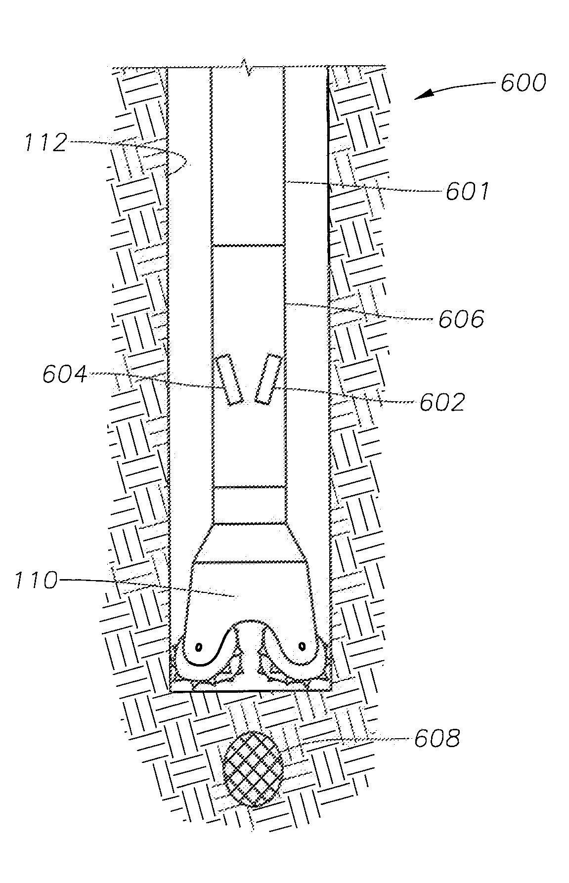
[0040]In accordance with the present disclosure, transient electromagnetic survey techniques and apparatus normally used in marine surveys may be modified to be deployed within a borehole 112, as illustrated schematically in embodiment 400 of FIG. 4. A dipole transmitter 402 is mounted on the drill string behind the drill bit 110, and EM receivers 404 and 406 are mounted below the dipole. The EM receivers 404, 406 measure a normally reflected wave in the axis of the drill string. This normally reflected wave would be off of resistivity contrasts directly in front of the bit. This would work very much like an acoustic VSP but working in the electromagnetic spectrum.

[0041]Another method to make a measurement in front of the bit would be to use modified continuous deep directional electromagnetic measurements. Deep directional electromagnetic (EM) tool measurements are known and explained, for example, in Omeragic et al., “Deep Directional Electromagnetic Measurements for Optimal Well ...

embodiment 800

[0044]FIG. 8 illustrates an embodiment 800 modified to focus energy in front of the bit and measure the formation resistivity ahead of the drill bit. Rather than sensing an oil / water contact, the reflected waves 85 would be reflected off of the top of a hydrocarbon formation 90.

[0045]In accordance with the present disclosure, a primary interest lies in using one or more of the methods and apparatus described above to obtain resistivity measurements in front of the drill bit to make drilling decisions on pore pressure and formation properties in front of the bit before the bit exposes the formation, which as discussed may create undesirable consequences in the well. The skilled operator or designer will determine which method and apparatus is best suited for a particular well and formation to achieve the highest efficiency without undue experimentation.

[0046]The actual calculation of pore pressure from resistivity is straightforward, one method being that described by Hottman et al. ...

embodiment 900

[0055]FIG. 9 illustrates one method embodiment 900 of the present disclosure in flowchart form. First, as indicated in box 902, the drilling supervisor, probably in conjunction with the mud engineer, geologist or other person in charge would choose initial drilling mud, and the driller would choose the drill bit. Apparatus for determining resistivity in front of the drill bit would be selected and installed in the drill string, either on-site or at a site removed from the well. In box 904, drilling is then begun, drilling toward a target formation at a known azimuth and dip angle using the selected drilling mud, drill bit, and resistivity apparatus. Box 906, resistivity data in front of the bit is gathered. Box 908, pore pressure in front of the bit is computed based on the measured resistivity in front of the bit. Box 910, one or more of density, specific gravity, weight, viscosity, water content, oil content, composition, pH, flow rate, solids content, solids particle size distrib...


PUM

PropertyMeasurementUnit
resistivityaaaaaaaaaa
anglesaaaaaaaaaa
pore pressureaaaaaaaaaa

Abstract

Methods are described using resistivity ahead of a drill bit measurements obtained while drilling a subterranean well using a drilling mud. Resistivity data ahead of the bit is gathered during drilling and prior to penetrating a region of interest of a known subterranean formation using the drill bit and the drilling mud. The drill string progresses at known dip and azimuth angles toward the subterranean formation. The resistivity data is used to determine pore pressure ahead of the drill bit in the formation as a function of resistivity ahead of the drill bit in the formation while the drill bit advances toward but before the bit penetrates the formation while drilling. In certain embodiments, the methods include redirecting the drill bit while drilling toward locations in the formation where pore pressure is within an acceptable range. In other embodiments, a drilling mud parameter is adjusted based on the pore pressure in front of the bit.

Description

CROSS-REFERENCE TO RELATED APPLICATIONS [0001]The present application is related to U.S. application Ser. Nos. ______ and ______, filed on even date herewith, and which are incorporated herein by reference in their entirety.BACKGROUND INFORMATION[0002]1. Technical Field[0003]The present disclosure relates in general to methods of drilling wellbores, for example, but not limited to, wellbores for producing hydrocarbons from subterranean formations, and more particularly to methods of using resistivity data ahead of the drill bit to determine pore pressure in the formation as a function of resistivity while the drill bit advances toward but before the bit penetrates a desired region in the formation while drilling.[0004]2. Background Art[0005]Hubbert et al., “Role of Fluid Pressure in Mechanics of Overthrust Faulting, Part I”, Bull., GSA (February 1959) 70, published a comprehensive treatment of the theory of compaction of clay soils by overburden pressure. They showed that as the ove...

Claims


Application Information

Patent Timeline
Patent Type & Authority Applications(United States)
IPC IPC(8): E21B7/00E21B49/00E21B7/04C09K8/02
CPCE21B21/08G01V3/20E21B47/06
Inventor ALBERTY, MARK WILLIAM
Owner BP CORP NORTH AMERICA INC
Why Eureka
Try Eureka