Device for coalescing fluids

a fluid-coalescing and fluid technology, applied in the direction of electrostatic separation, centrifuges, water/sludge/sewage treatment, etc., can solve the problems of affecting the electrical properties of the elements, and reducing the life of the devi

Inactive Publication Date: 2010-01-07
HAMWORTHY
View PDF11 Cites 4 Cited by
  • Summary
  • Abstract
  • Description
  • Claims
  • Application Information

AI Technical Summary

Benefits of technology

[0006]It is the main object of the present invention to provide a coalescer device that can operate at very high temperatures with an acceptable lifetime.
[0009]According to a preferred embodiment of the present invention, the tubular channel is made of a ceramic material, where the tube-shaped object is mounted in a box of stainless steel that comprises a coalescer device. The use of materials such as ceramics has several advantages apart from the ability to withstand high temperatures. Ceramics are well known for their chemical resistance and stable electrical properties. In addition, the ceramics have a very high arc resistance, which allows the use of very high field strengths.
[0026]According to another preferred embodiment, a layer is provided on said tubular channel, said layer having low permittivity, is electrically insulating and is able to withstand a strong electric field.

Problems solved by technology

However, epoxy resins are organic materials that degrade with time in harsh environments, e.g. crude oil processing.
The degradation affects the electrical properties of the elements, and may reduce the lifetime of the device.
Replacing the device is not always possible.
Sometimes it is not economically acceptable, or as in a subsea application, it is not physically feasible.
This can cause partial discharges in the emulsion and on the device itself.
Organic materials have a limited resistance towards partial discharges, which can limit the applied electric field in the device.
The coalescer modules described in NO 316109 are also costly to manufacture.
Moulds are costly and a new mould must be made for each design.
This also limits the number of workshops that may manufacture the modules, i.e. the production is limited to workshops that can manufacture moulding forms.

Method used


Image

  • Device for coalescing fluids
  • Device for coalescing fluids
  • Device for coalescing fluids

Examples


Embodiment Construction

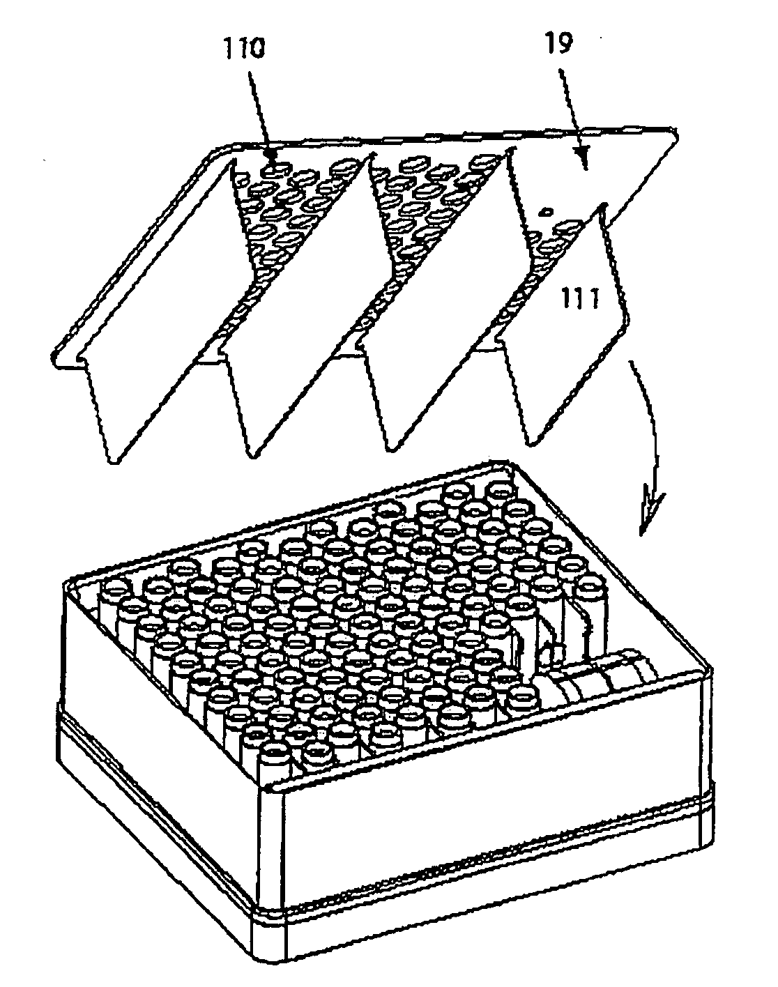
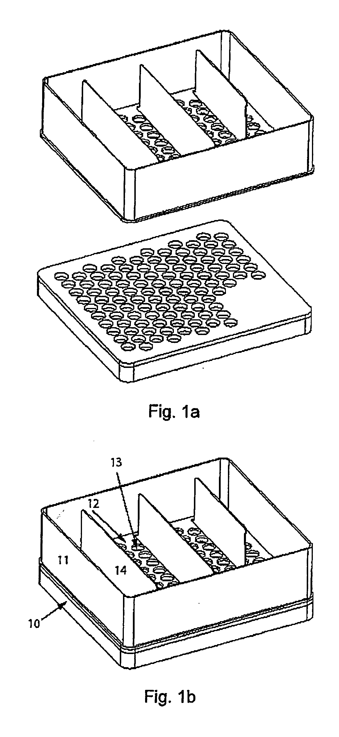
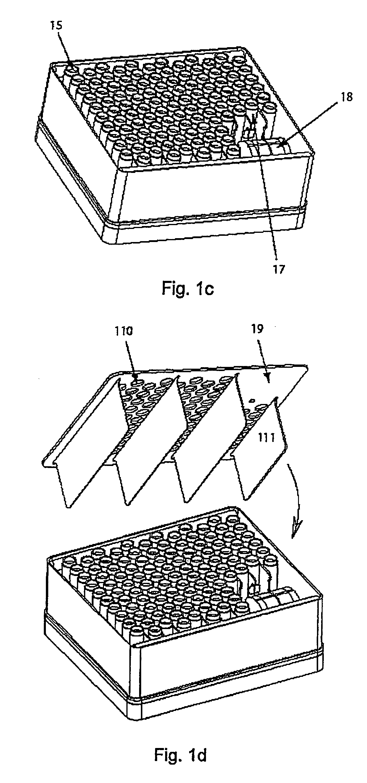
[0039]FIG. 1 shows the various components forming a coalescer module designed according to the present invention, and how they are assembled.

[0040]As shown in FIG. 1a, the module includes an installation plate 10 and a coalescer box mounted on said installation plate 10. The box includes a first end plate 12 and a wall 11. The installation plate and box may be made of stainless steel, e.g. 3 mm of thickness. As shown in FIG. 1b, the first end plate 12 includes a plurality of first mounting holes 13 and a number of first electrode plates 14 (grounded electrodes). As shown in FIG. 1c, in each first mounting hole 13 there will be mounted a coalescer tube 15 forming a channel through which the fluid mixture is intended to pass. In one part, such as a corner, of the box there is arranged a transformer 18. The transformer includes a primary winding connected to a primary source of electricity outside the coalescer, and a secondary high voltage winding connected to high voltage connectors ...


PUM


Abstract

A device for coalescing an emulsion component in an emulsion including a mixture of at least two different fluid components by an electric field applied to the emulsion. The device includes at least one electrostatic coalescer element. The coalescer element includes a tubular channel made of an electrically insulating material, a first electrode mounted on one side of the tubular channel, and a second electrode mounted on the other side of the tubular channel, a first end wall including a first opening adapted to receive a first end of the tubular channel, and a second end wall including a corresponding second opening adapted to receive a second end of the tubular channel. The walls together with the tubular channel isolate the emulsion from the electrodes.

Description

FIELD OF THE INVENTION[0001]The present invention relates to an electrically energized device for use in the separation of a first fluid emulsified in a second fluid with different dielectric properties. The invention may have a wide field of use, but it is particularly useful in the oil industry for removing water from a stream of oil and / or gas produced from a well.BACKGROUND OF THE INVENTION[0002]Fluids produced from an underground formation are usually a mixture of water, oil and gas (and sand), in which at least some of the water is emulsified in the oil. This mixture of fluids is usually separated into its components downstream of the wellhead, in order to be deliverable to pipe lines for further distribution. A possible method for performing such a separation is to use a multi-stage process involving a number of gravity separator tanks in succession. In order to improve the action of a gravity settling tank, the tank may be complemented with electrostatic coalescer devices.[0...

Claims


Application Information

Patent Timeline
Patent Type & Authority Applications(United States)
IPC IPC(8): B03C7/06
CPCB01D17/06B03C11/00B03C2201/02B03C7/04
Inventor NILSEN, PAL J.BJORKLUND, ERIK
Owner HAMWORTHY
Why Eureka
Try Eureka