Spherical aberration correction decelerating lens, spherical aberration correction lens system, electron spectrometer, and photoelectron microscope

a technology of spherical aberration and lens system, which is applied in the direction of instruments, magnetic discharge control, and beam deviation/focusing by electric/magnetic means, can solve the problems of insufficient atomic arrangement analysis, difficult to converge the beam, and the divergence angle of the beam is not sufficiently small, so as to improve the sensitivity and function of the photoelectron microscope

Inactive Publication Date: 2010-01-07
NARA INSTITUTE OF SCIENCE AND TECHNOLOGY
View PDF4 Cites 17 Cited by
  • Summary
  • Abstract
  • Description
  • Claims
  • Application Information

AI Technical Summary

Benefits of technology

[0032]According to this arrangement, by using the spherical aberration correction decelerating lens or the spherical aberration correction lens system which can accept a high energy beam with a large acceptance angle, it is possible to greatly enhance sensitivity and function of the photoelectron microscope.

Problems solved by technology

However, according to the foregoing conventional configuration, even if the einzel-type mesh lens can converge the beam having high energy over several hundreds eV and having a large divergence angle, the divergence angle of the beam does not become sufficiently small.
This raises a withstand-voltage problem in the electron lens, so that it is difficult to converge the beam.
This is insufficient for the atomic arrangement analysis.

Method used


Image

  • Spherical aberration correction decelerating lens, spherical aberration correction lens system, electron spectrometer, and photoelectron microscope
  • Spherical aberration correction decelerating lens, spherical aberration correction lens system, electron spectrometer, and photoelectron microscope
  • Spherical aberration correction decelerating lens, spherical aberration correction lens system, electron spectrometer, and photoelectron microscope

Examples


example 1

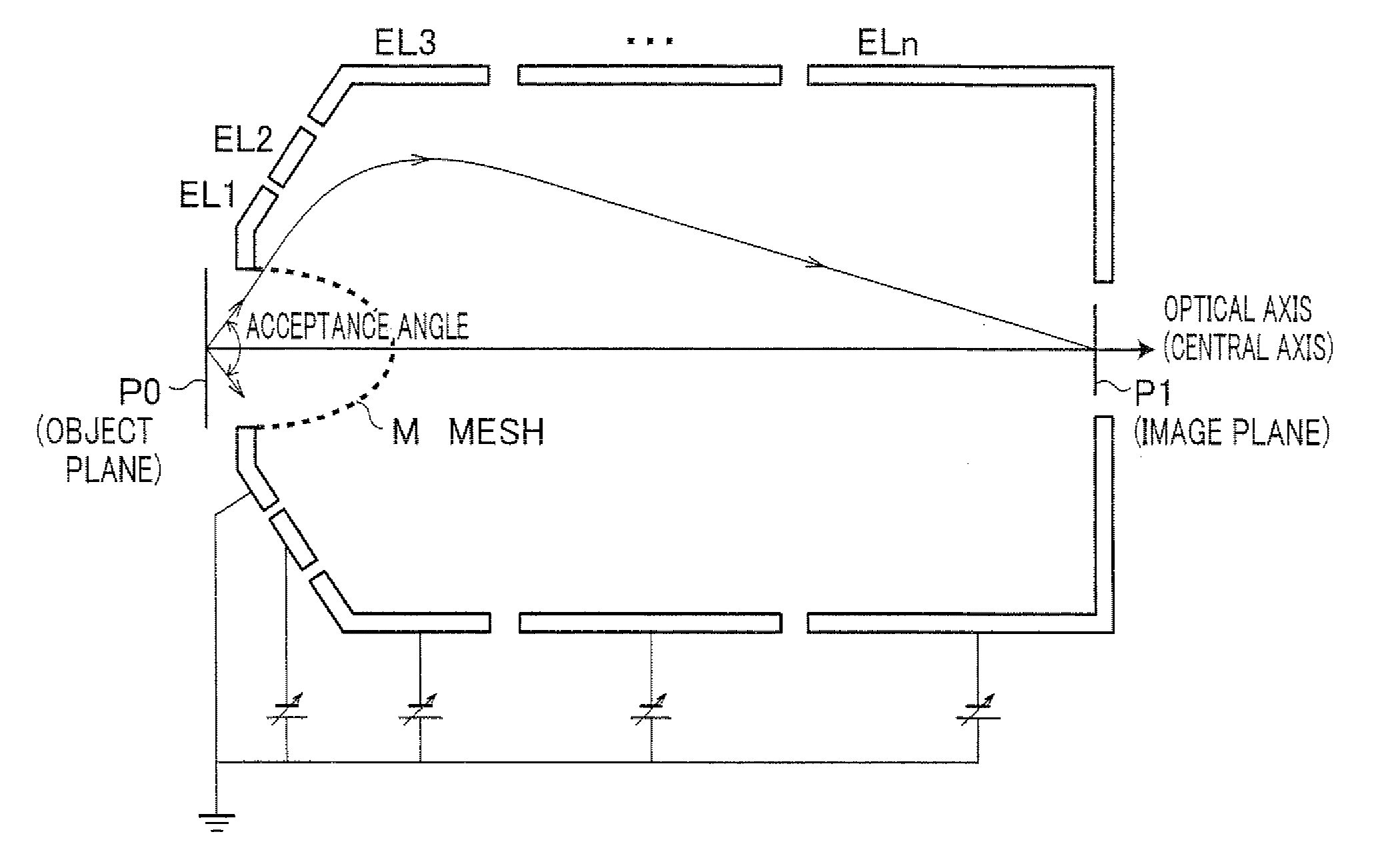
[0172]Herein, with reference to FIG. 11 to FIG. 14, Example 1 of the spherical aberration correction lens system of the present invention is described as follows. FIG. 11 is a cross sectional view schematically illustrating a spherical aberration correction lens system of Example 1. Note that, a curve in this figure indicates trajectories of a beam emitted from an object plane.

[0173]As illustrated in FIG. 11, the spherical aberration correction lens system of Example 1 includes a first lens E1 and a second lens E2.

[0174]The first lens E1 is constituted of the aforementioned spherical aberration correction decelerating lens of the present invention. In the spherical aberration correction decelerating lens, at least one of (i) a ratio of a major axis to a minor axis in a mesh M, (ii) a voltage applied to each electrode, (iii) a distance from an object plane P0 to the mesh M, and (iv) a length of each electrode is adjusted so that a negative spherical aberration occurs in an image plan...

example 2

[0186]With reference to FIG. 15(a) and FIG. 15(b), Example 2 of the spherical aberration correction lens system of the present invention is described as follows. FIG. 15(a) is a cross sectional view schematically illustrating a spherical aberration correction lens system of Example 2. FIG. 15(b) is a graph illustrating a relationship between an incident angle of a beam and a spherical aberration on the image plane P1 of the first lens E1 and a relationship between an incident angle of a beam and a spherical aberration on the image plane P2 of the second lens E2 in the spherical aberration correction system of Example 2. Note that, a continuous curve in this figure indicates trajectories of a beam emitted from an object plane.

[0187]As illustrated in FIG. 15(a), the spherical aberration correction lens system of Example 2 includes a first lens E1 and a second lens E2. The spherical aberration correction lens system of Example 2 is different from the spherical aberration correction len...

example 3

[0190]With reference to FIG. 16, Example 3 of the spherical aberration correction lens system of the present invention is described as follows. FIG. 16 is a cross sectional view schematically illustrating the spherical aberration correction lens system of Example 3. Note that, a curve in this figure indicates trajectories of a beam emitted from an object plane.

[0191]As illustrated in FIG. 16, the spherical aberration correction lens system of Example 3 includes a first lens E1 and a second lens E2. The spherical aberration correction lens system of the present Example is different from the spherical aberration correction lens system of Example 1 in an order in which the first lens EL1 and the second lens EL2 are arranged. That is, the first lens EL1 is constituted of at least one electron lens, and the second lens EL2 is constituted of the aforementioned spherical aberration correction decelerating lens of the present invention. In Example 3, the first lens EL1 is configured so as t...


PUM

PropertyMeasurementUnit
acceptance angleaaaaaaaaaa
distanceaaaaaaaaaa

Abstract

A spherical aberration correction decelerating lens corrects a spherical aberration occurring in an electron beam or an ion beam (hereinafter, referred to as “beam”) emitted from a predetermined object plane position with a certain divergence angle, and said spherical aberration correction decelerating lens comprises at least two electrodes, each of which is constituted of a surface of a solid of revolution whose central axis coincides with an optical axis and each of which receives an intentionally set voltage applied by an external power supply, wherein at least one of the electrodes includes one or more meshes (M) which has a concaved shape opposite to an object plane (P0) and which is constituted of a surface of a solid of revolution so that a central axis of the concaved shape coincides with the optical axis, and a voltage applied to each of the electrodes causes the beam to be decelerated and causes formation of a decelerating convergence field for correcting the spherical aberration occurring in the beam. This makes it possible to provide a spherical aberration correction decelerating lens which converges a beam, emitted from the sample and having high energy and a large divergence angle, onto an image plane.

Description

TECHNICAL FIELD[0001]The present invention relates to an input lens of (i) an electron spectrometer such as XPS (photoelectron spectrometer) and AES (Auger electron spectrometer) and (ii) PEEM (photoelectron microscope).BACKGROUND ART[0002]In a conventional photoelectron spectrometer, it is often that an electrostatic lens referred to as “input lens” is used for an input portion of an energy analyzer (represented by an electrostatic hemispherical analyzer). The input lens, first, accepts electrons emitted from a sample as much as possible and decelerates the electrons so that the decelerated electrons are incident on an analyzer, thereby enhancing an energy resolution ability.[0003]Further, there is a case where a function for limiting an electron acceptance angle in a sample surface is rendered to the electron spectrometer. In the electron spectrometer configured in this manner, its sensitivity is determined depending on a divergence angle (a solid angle) of electrons that the inpu...

Claims


Application Information

Patent Timeline
Patent Type & Authority Applications(United States)
IPC IPC(8): H01J3/18G01N23/00
CPCH01J37/12H01J37/252H01J2237/05H01J2237/2538H01J2237/1532H01J2237/244H01J2237/2511H01J2237/153
Inventor MATSUDA, HIROYUKIDAIMON, HOROSHI
Owner NARA INSTITUTE OF SCIENCE AND TECHNOLOGY
Why Eureka
Try Eureka