
GPS module test system for automatically calibrating test signal

a test signal and module technology, applied in wave based measurement systems, instruments, special-purpose recording/indication apparatus, etc., can solve the problems of reducing the db value, testers are unable to control satellite signal simulators to adjust the rf power, test fixtures do not have the function of auto calibration, etc., to enhance the accuracy of module test and facilitate replacement

Active Publication Date: 2010-01-07
ALTEK (KUNSHAN) CO LTD
View PDF9 Cites 12 Cited by
  • Summary
  • Abstract
  • Description
  • Claims
  • Application Information

AI Technical Summary

Benefits of technology

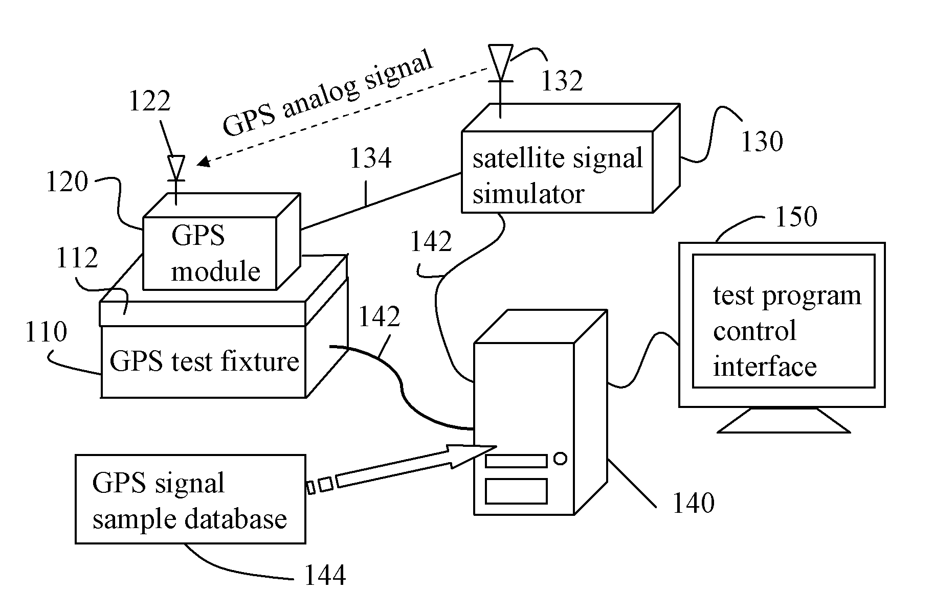
[0007]In order to solve the above problems that it is time and energy consuming to test a GPS module, and the fixture cannot be automatically calibrated, the present invention is directed to a GPS module test system for automatically calibrating a test signal. A GPS test fixture carries and electrically connects a device under test through contact, so as to simplify the process of testing a GPS module. When a digital signal is attenuated, a computer controls a satellite signal simulator to dynamically gain a transmitted GPS analog signal, thereby enhancing the test accuracy.
[0013]Based on the above, the GPS module test system for automatically calibrating a test signal provided by the present invention employs a GPS test fixture to carry and electrically connect a GPS module under test without welding, so the GPS module under test can be easily replaced. In addition, the computer in the GPS module test system determines whether the GPS signal is attenuated according to a digital signal generated by the GPS module under test, so as to dynamically calibrate the GPS analog signal for testing the GPS module and thus enhance the precision of the module test.

Problems solved by technology

However, since the GPS signal is a quite weak satellite signal, production problems must be taken into consideration on the design of the GPS module, so as to make sure that the designed / produced GPS module is usable (i.e., the GPS module is able to correctly receive and resolve a weak GPS signal).
Thus, the welding quality may directly influence the test quality of the GPS module (affecting the receiving power of the GPS module, and thus reducing the db value thereof).
In addition, a tester is unable to control a satellite signal simulator to adjust the RF power, and a test fixture does not have the function of auto calibration (i.e., to confirm that the sensitivity of this test is the same as that of the previous one).
Further, the conventional test fixture does not have the function of automatically determining pass / failure (i.e., automatically determining whether the GPS module is qualified), and cannot test GPS modules repeatedly.
Thus, when another GPS module is to be tested, the previously tested GPS module must be disordered first, and then the GPS module under test is welded, so the operation is rather troublesome.

Method used


Image

  • GPS module test system for automatically calibrating test signal
  • GPS module test system for automatically calibrating test signal
  • GPS module test system for automatically calibrating test signal

Examples


Embodiment Construction

[0018]The objectives of the present invention and the provided GPS module test system will be illustrated in detail in the following preferred embodiments. However, the concept of the present invention may also be applied in other scopes. The following embodiments are merely used to illustrate the objectives and implementation of the present invention, instead of limiting the scope of the same.

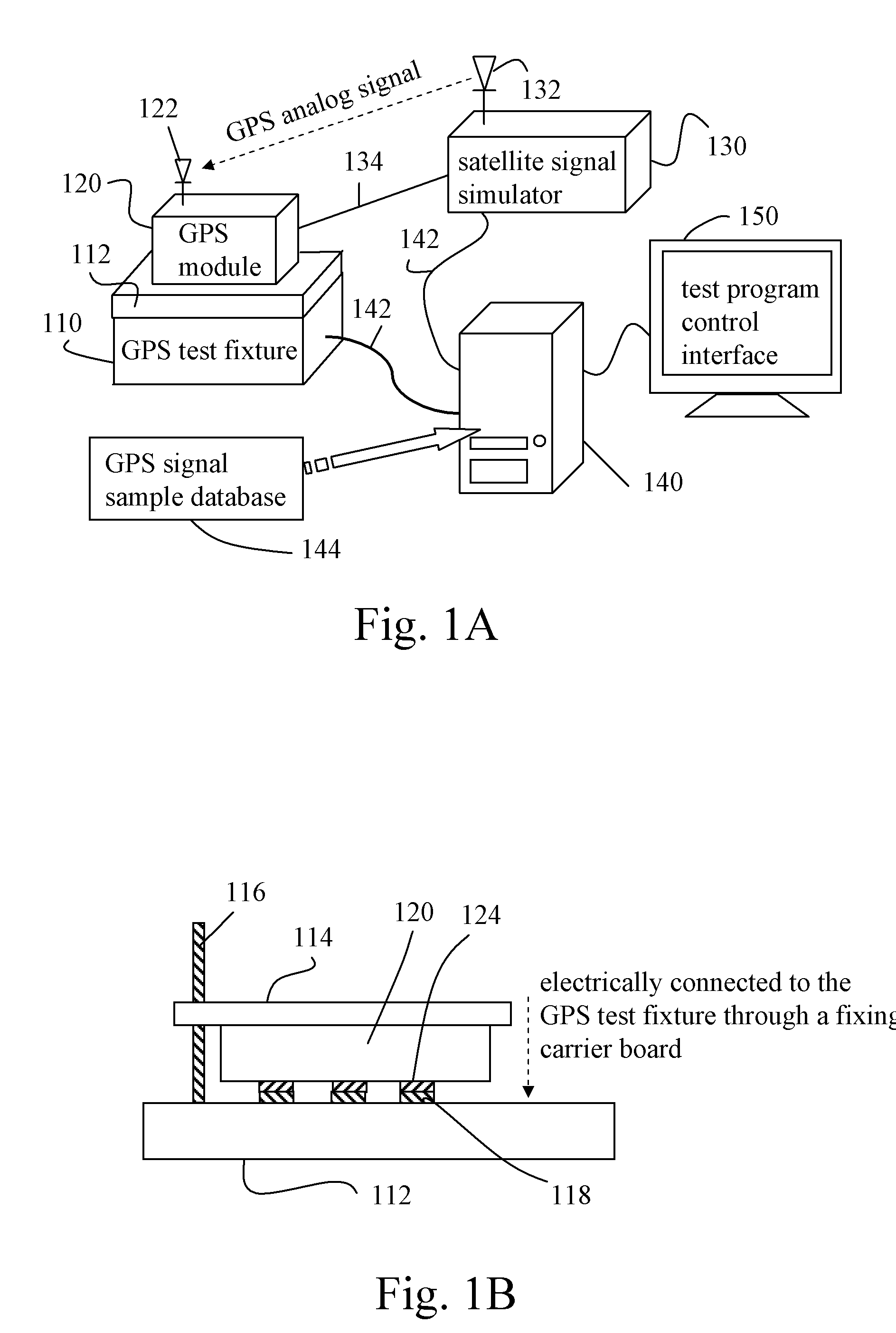
[0019]FIG. 1A is a schematic view showing the architecture of a GPS module test system for automatically calibrating a test signal according to a preferred embodiment of the present invention. Referring to FIG. 1A, in this embodiment, the GPS module test system for calibrating a test signal includes a GPS test fixture 110, a satellite signal simulator 130, and a computer 140 for controlling a test process. The GPS test fixture 110 has a carrier board 112 disposed thereon for carrying a GPS module under test 120. Further, the GPS test fixture 110 has a plurality of metal contact pads (not shown...


PUM


Abstract

A GPS module test system for automatically calibrating a test signal includes a GPS test fixture, a satellite signal simulator, and a computer. The GPS test fixture carries a GPS module under test and is electrically connected to the same through contact, so as to receive a digital signal generated by the GPS module after the test. The computer receives device information of the GPS module under test through the GPS test fixture, and controls the satellite signal simulator through a GPS signal sample database, so as to generate a GPS analog signal to test the GPS module under test. Thereafter, on receiving the digital signal generated by the GPS module under test and determining the received digital signal is attenuated, the computer automatically gains a transmitted test parameter, so as to transmit the GPS analog signal in a preferable state.

Description

CROSS-REFERENCE TO RELATED APPLICATIONS[0001]This non-provisional application claims priority under 35 U.S.C. § 119(a) on Patent Application No(s). 096148077 filed in Taiwan, R.O.C. on Dec. 14, 2007, the entire contents of which are hereby incorporated by reference.BACKGROUND OF THE INVENTION[0002]1. Field of Invention[0003]The present invention relates to a GPS module test system, and more particularly to a GPS module test system for automatically calibrating a test signal.[0004]2. Related Art[0005]Global position system (GPS) is a kind of technology for precisely positioning the coordinates of an object, such as a vehicle or a ship. The earlier GPS technology was developed by the United States Department of Defense for military purposes. Now, the GPS technology switches to civil applications from the military fields, for example, map navigation. Some electronic equipments, such as personal digital assistants (PDAs), computers, mobile phones, and watches, are all provided with a mi...

Claims


Application Information

Patent Timeline
IPC IPC(8): G01S7/40G01S1/00
CPCG01S19/235
Inventor FU, YU-BANGLIN, HAO-CHIH
Owner ALTEK (KUNSHAN) CO LTD
Learn More