Coaxial line slot array antenna and method for manufacturing the same

a technology of coaxial line and array antenna, which is applied in the direction of slot antenna, linear waveguide fed array, antenna, etc., can solve the problems of difficult adjustment of probe length and complicated structure of use, and achieve low loss and low profile

Active Publication Date: 2010-01-07
MITSUBISHI ELECTRIC CORP
View PDF9 Cites 44 Cited by
  • Summary
  • Abstract
  • Description
  • Claims
  • Application Information

AI Technical Summary

Benefits of technology

[0018]According to the present invention, the planar antenna formed with slot arrays capable of setting a narrow interval between elements so as to perform beam scanning in a wide angle range can be formed while keeping low loss and low profile.

Problems solved by technology

However, use of the probe complicates a structure and makes adjustment of a probe length difficult.

Method used


Image

  • Coaxial line slot array antenna and method for manufacturing the same
  • Coaxial line slot array antenna and method for manufacturing the same
  • Coaxial line slot array antenna and method for manufacturing the same

Examples


first embodiment

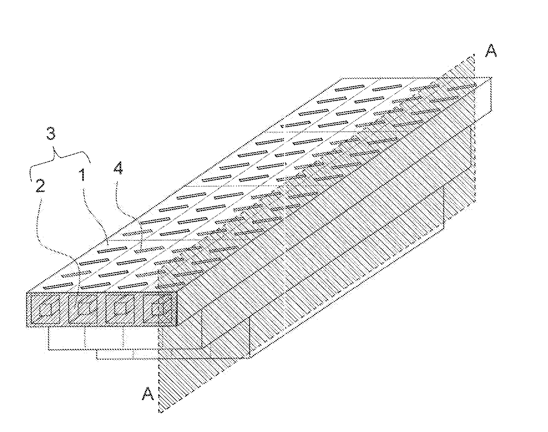
[0032]FIG. 1 is a perspective view illustrating a structure of a coaxial line slot array antenna according to a first embodiment of the present invention. In FIG. 1, a coaxial line 3 formed of a square coaxial line is formed of an outer conductor 1 and an inner conductor 2, and slots 4 are provided on a wall surface of the outer conductor 1, which forms a radiation surface.

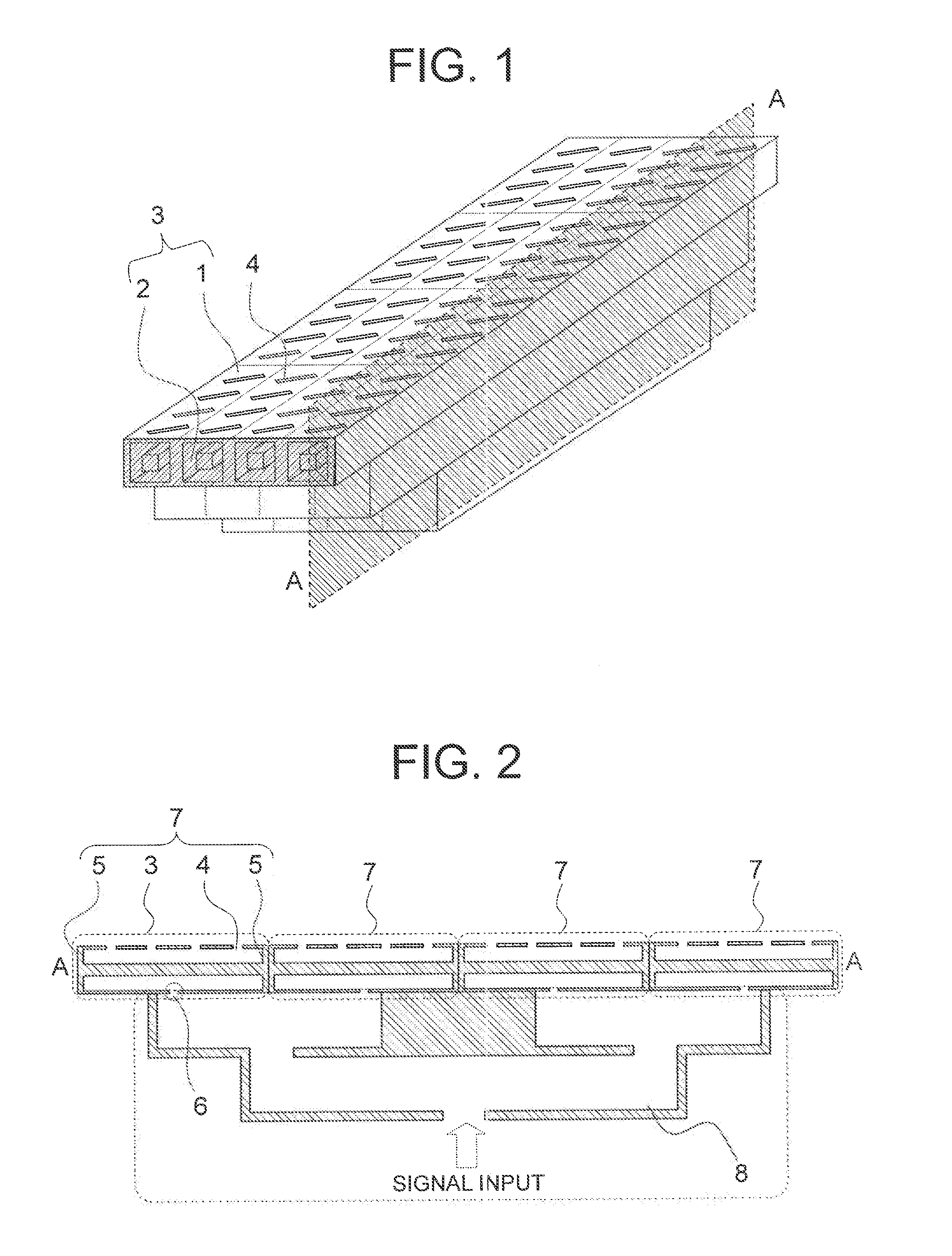
[0033]FIG. 2 is a cross-sectional view taken along A-A of FIG. 1. As illustrated in FIG. 2, both end surfaces of the coaxial line 3 are short-circuited by a short-circuit plate 5, and a coupling hole 6 is provided in the coaxial line 3 to be fed by feeding means (a waveguide is assumed here). A coaxial line slot array antenna per unit is formed of the coaxial line 3, the slots 4, the short-circuit plates 5, and the coupling hole 6 for feeding connected to the feeding means. Hereinafter, this is called a sub-array 7. As described above, a feed circuit 8 serving as the feeding means, which is formed of the waveguide...

second embodiment

[0061]In the first embodiment described above, the description has been given of the structure of the coaxial line slot array antenna excited by the standing wave. Next, a method of manufacturing this antenna is described.

[0062]FIG. 11 are a cross-sectional view for illustrating a method of manufacturing a coaxial line slot array antenna according to a second embodiment of the present invention and an exploded cross-sectional view of a part of the antenna. Here, a waveguide is used as a feeding technique for the coaxial line.

[0063]In the exploded cross-sectional view of FIG. 11, respective portions are divided and sliced into a plate shape so as to parallel to the tube axis of the square coaxial line and also parallel to the side surface of the outer conductor in which the slots are provided, and are formed by a step of individually cutting seven metal conductor plates. For simplification of explanation, only two sub-arrays within one row are illustrated in the figure. Through a ste...


PUM

PropertyMeasurementUnit
circumferenceaaaaaaaaaa
resonance lengthaaaaaaaaaa
wavelengthaaaaaaaaaa

Abstract

A planar antenna including slot arrays configured to set a narrow interval between elements so as to perform beam scanning in a wide angle range while keeping low loss and low profile. The planar antenna includes: a coaxial line including an inner conductor, an outer conductor provided so as to surround a circumference of the inner conductor, and both ends short-circuited; a feeding mechanism for exciting the coaxial line; and a plurality of slots formed on the outer conductor with a certain angle with respect to a tube direction of the coaxial line and having approximately a resonance length.

Description

TECHNICAL FIELD[0001]The present invention relates to a coaxial line slot array antenna formed of a plurality of slots in a coaxial line, and to a method of manufacturing the same.BACKGROUND ART[0002]As an antenna system related to a coaxial line slot array antenna, there is generally known a waveguide slot array antenna (for example, see Patent Document 1). In this waveguide slot array antenna, a waveguide, a short-circuit plate for short-circuiting both ends of the waveguide, and slots provided in a wide wall surface of the waveguide are combined to form a sub-array. There is provided a feed circuit as feeding means for the sub-arrays, and the respective sub-arrays and the feed circuit provided to the sub-arrays are combined to form a waveguide slot array type planar array antenna.[0003]This antenna is uniformly excited when an input signal is uniformly transmitted to the feed circuit provided to the respective sub-arrays through a signal path. In a waveguide slot array which is a...

Claims


Application Information

Patent Timeline
Patent Type & Authority Applications(United States)
IPC IPC(8): H01Q13/10H01P11/00
CPCH01Q13/12Y10T29/49016H01Q13/203H01Q21/005H01P3/06H01P5/08H01Q13/10H01Q21/08
Inventor YAMAGUCHI, SATOSHITAHARA, YUKIHIRONISHIZAWA, KAZUSHIMIYASHITA, HIROAKIOOHASHI, HIDEYUKI
Owner MITSUBISHI ELECTRIC CORP
Why Eureka
Try Eureka