Optical system of atomic oscillator and atomic oscillator

Inactive Publication Date: 2010-01-07
SEIKO EPSON CORP
View PDF5 Cites 16 Cited by
  • Summary
  • Abstract
  • Description
  • Claims
  • Application Information

AI Technical Summary

Benefits of technology

[0007]An advantage of the present invention is to provide an optical system of an atomic oscillator, in which a fluorescence blocking unit is provided at an emitting side of a gas cell so as to prevent fluorescence as leaked light from entering a light detector and thus improve an S/N ratio of transmitted light.
[0008]The invention can be achieved by following aspects.
[0009]An optical system, according to a first aspect of the invention, of an atomic oscillator that regulates an oscillation frequency by using an optical absorption property by one of a double resonance method utilizing light and micro waves and a coherent population trapping (CPT) method utilizing a quantum interference effect produced by two kinds of resonance light, includes: a light source emitting the resonance light; a gas cell disposed at an emitting side of the light source, sealing a gaseous metal atom therein and transmitting the resonance light through a metal atom gas; a light detecting unit detecting the transmitted light that is transmitted through the metal atom gas; and a fluorescence blocking unit blocking at least a part of fluorescence, which is emitted from the metal atom gas to the light detecting unit, and disposed between the metal atom gas and the light detecting unit.
[0010]When the resonance light h

Problems solved by technology

The fluorescence is incident on the light detector as leaked light, so that a level of primary transmitted light is increased, resulting in degradation of an S/N ratio of a detecting signal.
Thus the related art has not solved the problem of the degradation of an S/N ratio of the transmitted light.
The fluorescence is incident on the light detect

Method used


Image

  • Optical system of atomic oscillator and atomic oscillator
  • Optical system of atomic oscillator and atomic oscillator
  • Optical system of atomic oscillator and atomic oscillator

Examples


first embodiment

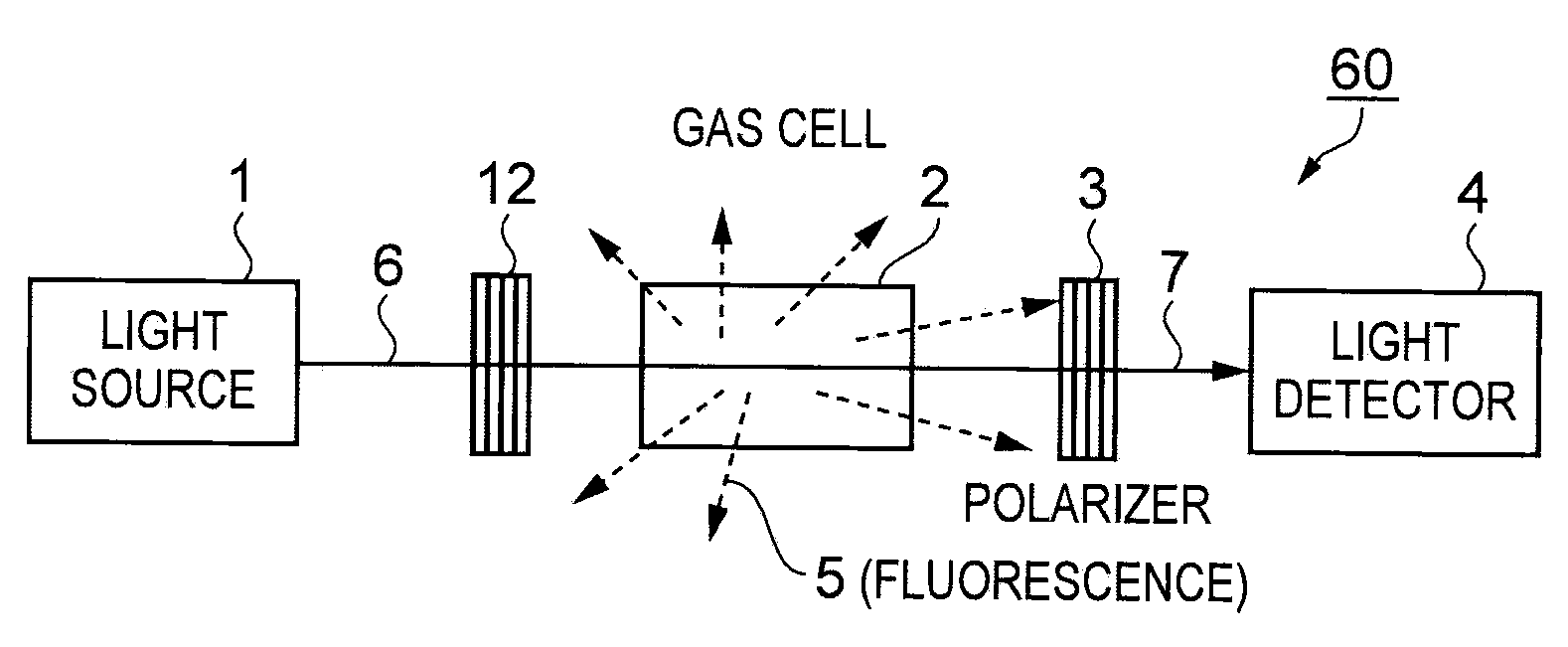
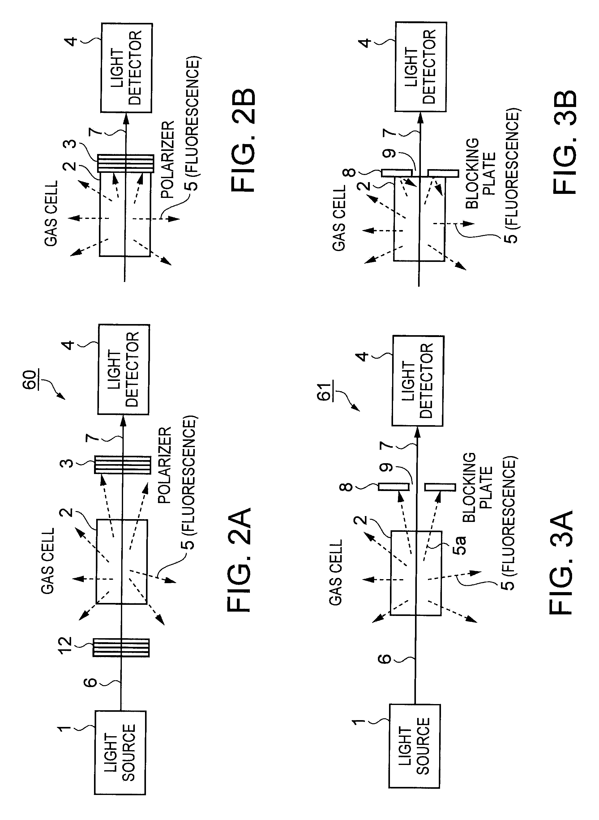
[0036]FIG. 2A is a diagram schematically showing a structure of an optical system according to a first embodiment of the invention. FIG. 2B is a diagram showing a structure in which a polarizer is closely attached to a gas cell. This optical system 60 is included in an atomic oscillator that regulates an oscillation frequency by using an optical absorption property by a double resonance method utilizing light and micro waves or a CPT method utilizing quantum interference effect produced by two kinds of resonance light. The optical system 60 includes: a light source 1 emitting resonance light 6; a polarizer 12 polarizing the resonance light 6 in a predetermined vibrating direction; the gas cell 2 disposed at an emitting side of the light source 1, sealing a gaseous metal atom therein and transmitting the resonance light 6 through a metal atom gas; a light detector 4 serving as a light detecting unit detecting transmitted light 7 that is transmitted through the gas cell 2; and a polar...

second embodiment

[0038]FIG. 3A is a diagram schematically showing a structure of an optical system according to a second embodiment of the invention. FIG. 3B is a diagram showing a structure in which a blocking plate is closely attached to a gas cell. Elements same as those in FIGS. 2A and 2B are given the same reference numbers and explained. This optical system 61 is included in an atomic oscillator that regulates an oscillation frequency by using an optical absorption property by a double resonance method utilizing light and micro waves or a CPT method utilizing quantum interference effect produced by two kinds of resonance light. The optical system 61 includes: the light source 1 emitting the resonance light 6; the gas cell 2 disposed at the emitting side of the light source 1, sealing a gaseous metal atom therein and transmitting the resonance light 6 through a metal atom gas; the light detector 4 serving as a light detecting unit detecting the transmitted light 7 that is transmitted through th...

third embodiment

[0040]FIG. 4A is a diagram schematically showing a structure of an optical system according to a third embodiment of the invention. FIG. 4B is a diagram showing a structure in which a blocking plate and a polarizer are closely attached to a gas cell. Elements same as those in FIGS. 2A and 2B are given the same reference numbers and explained. This optical system 62 is included in an atomic oscillator that regulates an oscillation frequency by using an optical absorption property by a double resonance method utilizing light and micro waves or a CPT method utilizing quantum interference effect produced by two kinds of resonance light. The optical system 62 includes: the light source 1 emitting the resonance light 6; the polarizer 12 polarizing the resonance light 6 in a predetermined vibrating direction; the gas cell 2 disposed at the emitting side of the light source 1, sealing a gaseous metal atom therein and transmitting the resonance light 6 through a metal atom gas; the light det...


PUM


Abstract

An optical system of an atomic oscillator that regulates an oscillation frequency by using an optical absorption property by one of a double resonance method utilizing light and micro waves and a coherent population trapping (CPT) method utilizing a quantum interference effect produced by two kinds of resonance light, includes: a light source emitting the resonance light; a gas cell disposed at an emitting side of the light source, sealing a gaseous metal atom therein and transmitting the resonance light through a metal atom gas; a light detecting unit detecting the transmitted light that is transmitted through the metal atom gas; and a fluorescence blocking unit blocking at least a part of fluorescence, which is emitted from the metal atom gas to the light detecting unit, and disposed between the metal atom gas and the light detecting unit.

Description

BACKGROUND[0001]1. Technical Field[0002]The present invention relates to an optical system of an atomic oscillator, in particular, relates to a structural technique by which an SIN ratio of transmitted light emitted from a gas cell included in the atomic oscillator is improved.[0003]2. Related Art[0004]Atomic oscillators using alkali metals such as rubidium and cesium operate while maintaining a gas cell, in which atoms are air-tightly sealed, at a high temperature because the atoms need to be kept in a gas state when the oscillators use energy transition of the atoms. An operating principle of the atomic oscillators is broadly classified into a double resonance method utilizing light and micro waves and a method utilizing quantum interference effect produced by two kinds of laser light (hereinafter, referred to as coherent population trapping: CPT). In both of the methods, atomic resonance is detected by detecting how much light made incident on the gas cell is absorbed by atom gas...

Claims


Application Information

Patent Timeline
IPC IPC(8): G01J4/00
CPCH03L7/26G04F5/145
Inventor CHINDO, KOJI
Owner SEIKO EPSON CORP
Why Eureka
Try Eureka