Trans-Vertebral and Intra-Vertebral Plate and Fusion Cage Device for Spinal Interbody Fusion and Method of Operation

a technology of transvertebral plate and fusion cage, which is applied in the field of transvertebral plate and intravertebral plate and fusion cage, can solve the problems of loosened screws inside the vertebral body or broken screws at the screw-rod junction results that are not uncommon, and surrounding soft tissues, and achieves enhanced fusion, simple operation, and limited intervertebral movement.

Inactive Publication Date: 2010-01-07
LIN JIN FU +1
View PDF8 Cites 104 Cited by
  • Summary
  • Abstract
  • Description
  • Claims
  • Application Information

AI Technical Summary

Benefits of technology

[0008]The present invention improves upon known screw based spinal fixation devices, which are bulky, complicated in design and handling, for the purpose of limiting intervertebral movement. In a basic form of embodiment, the present invention is a plate device, which is trans-vertebral and intra-vertebral and coupled to a rectangular cage in which there is a slot to accommodate the plate. After inserting the cage into the intervertebral space, one of the longer ends of the plate is placed through the slot of the cage, and perpendicularly facing cortical bones of two adjacent vertebral bodies. The plate device is then hammered and penetrating the cortical bones from lateral or anterior side of the two adjacent vertebral bodies, and the plate device is buried inside the vertebral

Problems solved by technology

First, the inherent biomechanical weaknesses of the bone screw include: the contact area of the bone screw is small and about one-tenth of its circumferential diameter in any direction of intervertebral movement; and the weight-loading stress of the screws is transferred to and concentrated at the screw-rod or screw-plate junction, and thus loosened screws inside the vertebral body or broken screws at the screw-rod junction results are not uncommon.
Second, during implanting the screw fixation devices into the spinal column, surrounding soft tissues may be injured, and anterior inserted systems may injure the great vessels and posterior inserted systems may jeopardize the nerves.
Third, the screw fixation devices are bul

Method used


Image

  • Trans-Vertebral and Intra-Vertebral Plate and Fusion Cage Device for Spinal Interbody Fusion and Method of Operation
  • Trans-Vertebral and Intra-Vertebral Plate and Fusion Cage Device for Spinal Interbody Fusion and Method of Operation
  • Trans-Vertebral and Intra-Vertebral Plate and Fusion Cage Device for Spinal Interbody Fusion and Method of Operation

Examples


Embodiment Construction

[0016]The above and other objects, features and advantages of the present invention will become apparent from the following detailed description taken with the accompanying drawing.

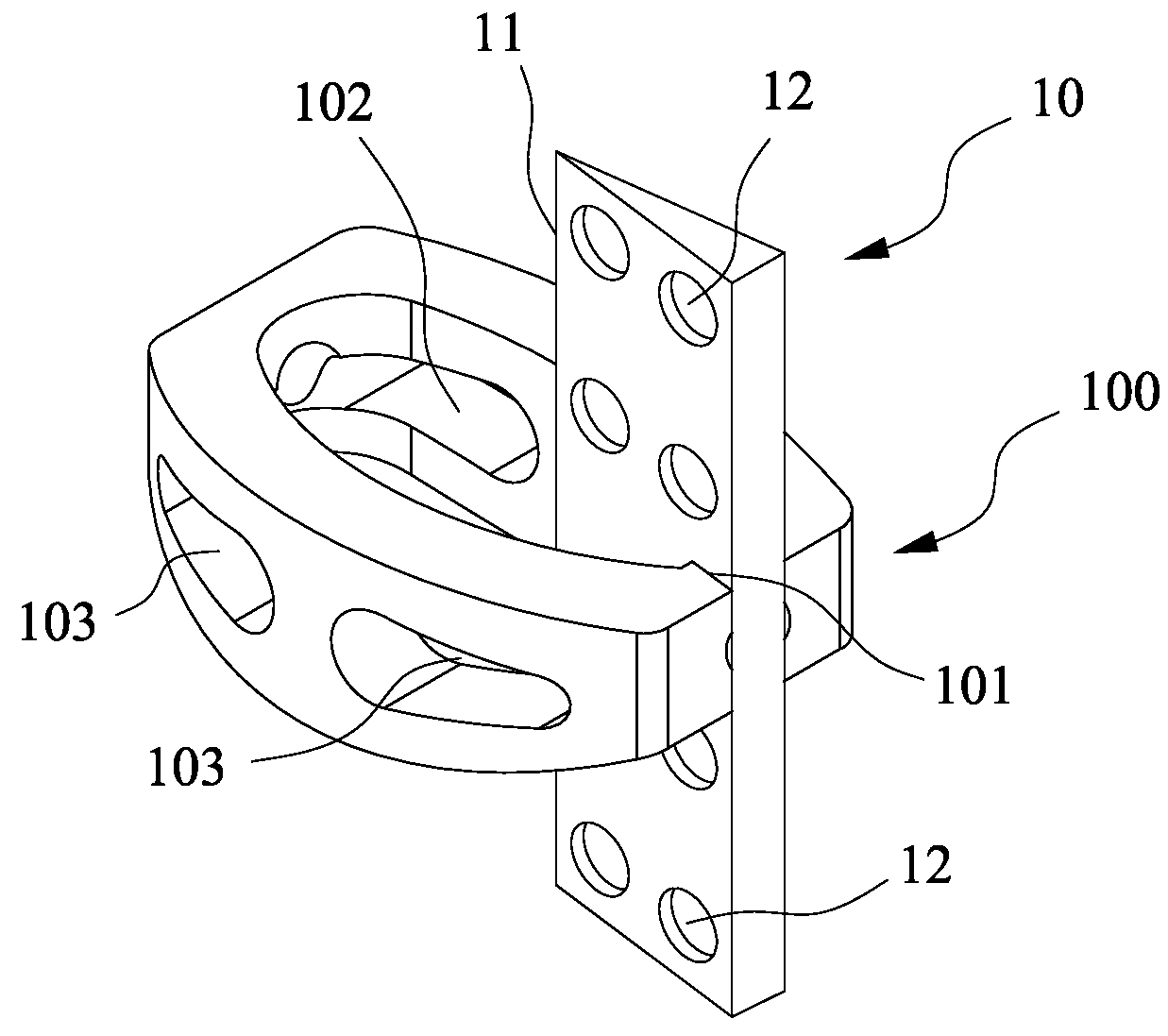
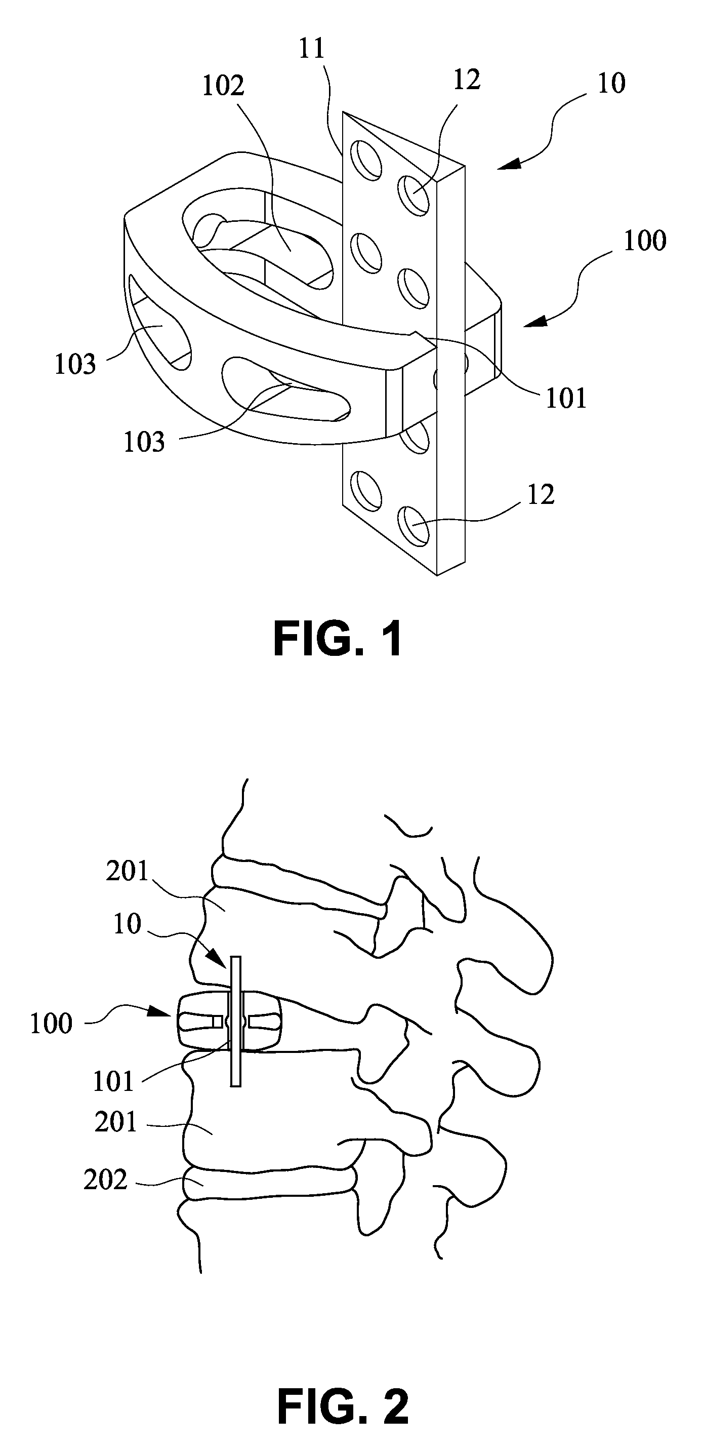
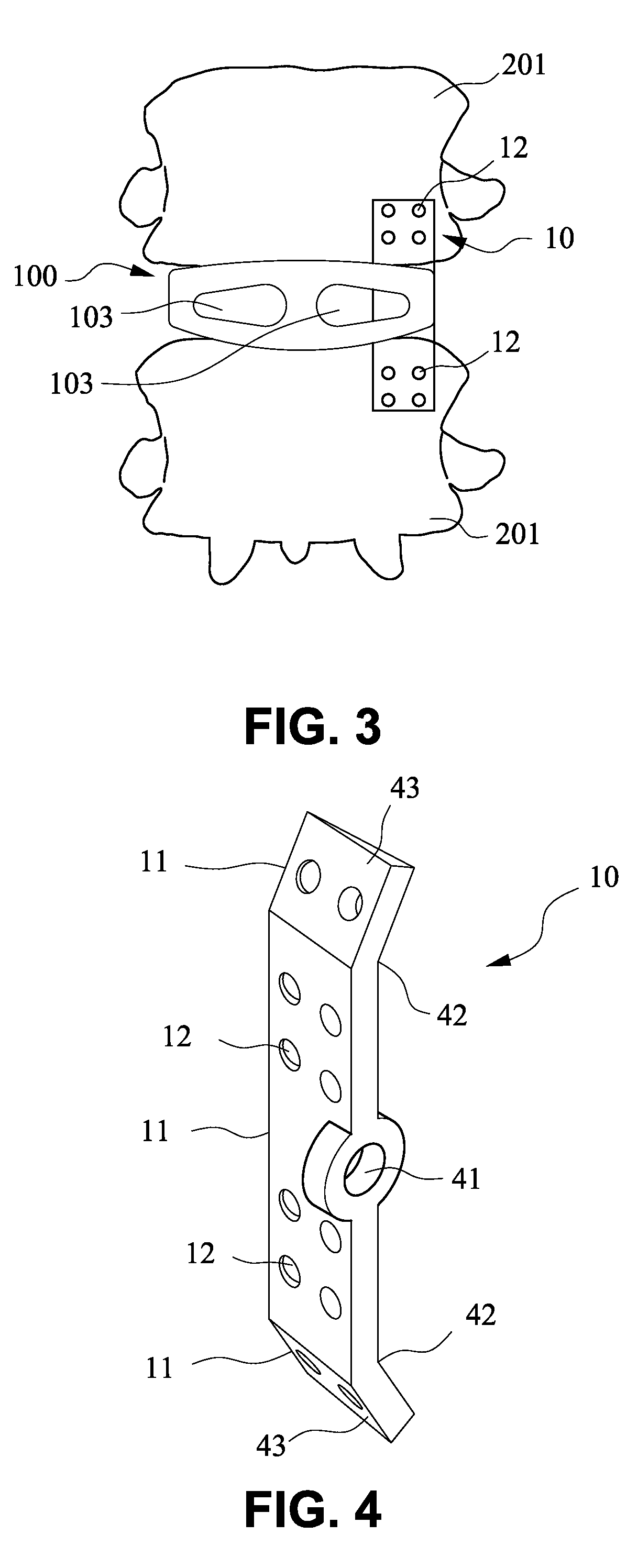
[0017]FIG. 1 shows a preferred embodiment of the present invention which comprises a trans-vertebral and intra-vertebral plate (10) and a rectangular cage (100) with a vertical slot (101) to accommodate the plate (10). The trans-vertebral and intra-vertebral plate (10) has one of its longer ends thinned (11) for the purpose of ease of penetrating into two adjacent vertebral bodies, and the thinned end is facing the cortical bones of the vertebral bodies during insertion. The surface of the plate is perforated (12) to facilitate bone ingrowth through the holes (12). The rectangular cage (100) has a vertical slot (101) on its lateral end to accommodate the plate (10), and the cage also has holes (103) to facilitate bone ingrowth. The plate and the cage can be made of any biocompatible materials such as tita...


PUM


Abstract

A trans-vertebral and intra-vertebral plate and a rectangular cage with a slot for the plate of spinal fixation device are for neutralizing intervertebral movement for the spinal interbody fusion. The rectangular cage with a vertical or oblique slot is inserted into the intervertebral space from the lateral or anterior side of the spinal column and then the plate is inserted through the slot of the cage and hammered into and buried inside two adjacent vertebral bodies, to achieve three-dimensional intervertebral fixation.

Description

CROSS-REFERENCE TO RELATED APPLCATIONS[0001]Not applicableSTATEMENT REGARDING FEDERALLY SPONSORED RESEARCH[0002]Not applicableFIELD OF THE INVENTION [0003]The present invention relates to spinal fusion, and more particularly to a trans-vertebral and intra-vertebral plate and a fusion cage with a slot for the plate and the method of operation. The cage with a slot for the plate is inserted into the interbody space and the trans-vertebral and intra-vertebral structure is implanted inside two adjacent vertebral bodies through the slot of the cage, to provide intervertebral stability by limiting or neutralizing intervertebral movement in order to enhance the fusion, specifically for a device which utilizes a trans-vertebral and intra-vertebral plate and a fusion cage element.BACKGROUND OF THE INVENTIONDescription of the Prior Art[0004]Spinal interbody fusion is a commonly performed procedure for degenerative disorders. To achieve a successful fusion, a spinal fixation device is usually ...

Claims


Application Information

Patent Timeline
IPC IPC(8): A61F2/44A61B17/70A61B17/04
CPCA61B17/7059A61F2310/00023A61F2002/30281A61F2002/30433A61F2002/30507A61F2002/30576A61F2002/30594A61F2002/30604A61F2002/30777A61F2002/30785A61F2002/30848A61F2002/30884A61F2002/30899A61F2002/30904A61F2220/0025A61F2220/0041A61F2230/0086A61F2/4465A61F2002/30845
Inventor LIN, JIN-FU
Owner LIN JIN FU
Why Eureka
Try Eureka