Filtering device

a filter element and filtering technology, applied in the direction of filtering separation, moving filter element filters, separation processes, etc., can solve the problems of affecting etc., to achieve the effect of reducing the axial length of the filter element, reducing the required mounting space in the axial direction, and improving the flow rate of the filter elemen

Inactive Publication Date: 2010-01-14
MANN HUMMEL GMBH
View PDF46 Cites 5 Cited by
  • Summary
  • Abstract
  • Description
  • Claims
  • Application Information

AI Technical Summary

Benefits of technology

[0013]According to a further advantageous embodiment the filter wall of the hose-shaped filter element can have an additional fastening site relative to a component that, in particular, is also the support part. In this embodiment, not only an axial end face of the filter element is annularly and seal-tightly secured on the support part but at least one part of the filter element is connected at an additional fastening site to the support part. As a result, this lead...

Problems solved by technology

Improper seating of the support part between the fluid pipes, for examp...

Method used


Image

  • Filtering device
  • Filtering device
  • Filtering device

Examples


Embodiment Construction

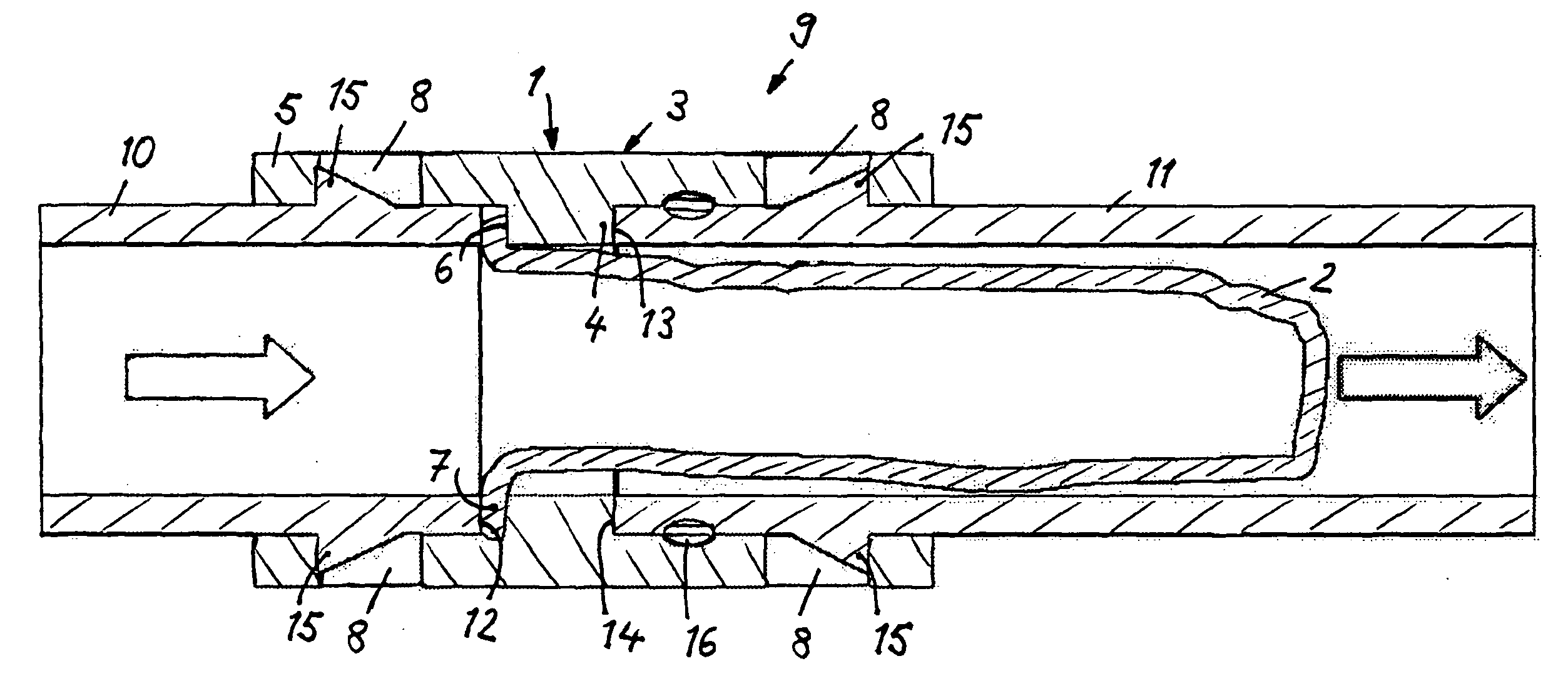
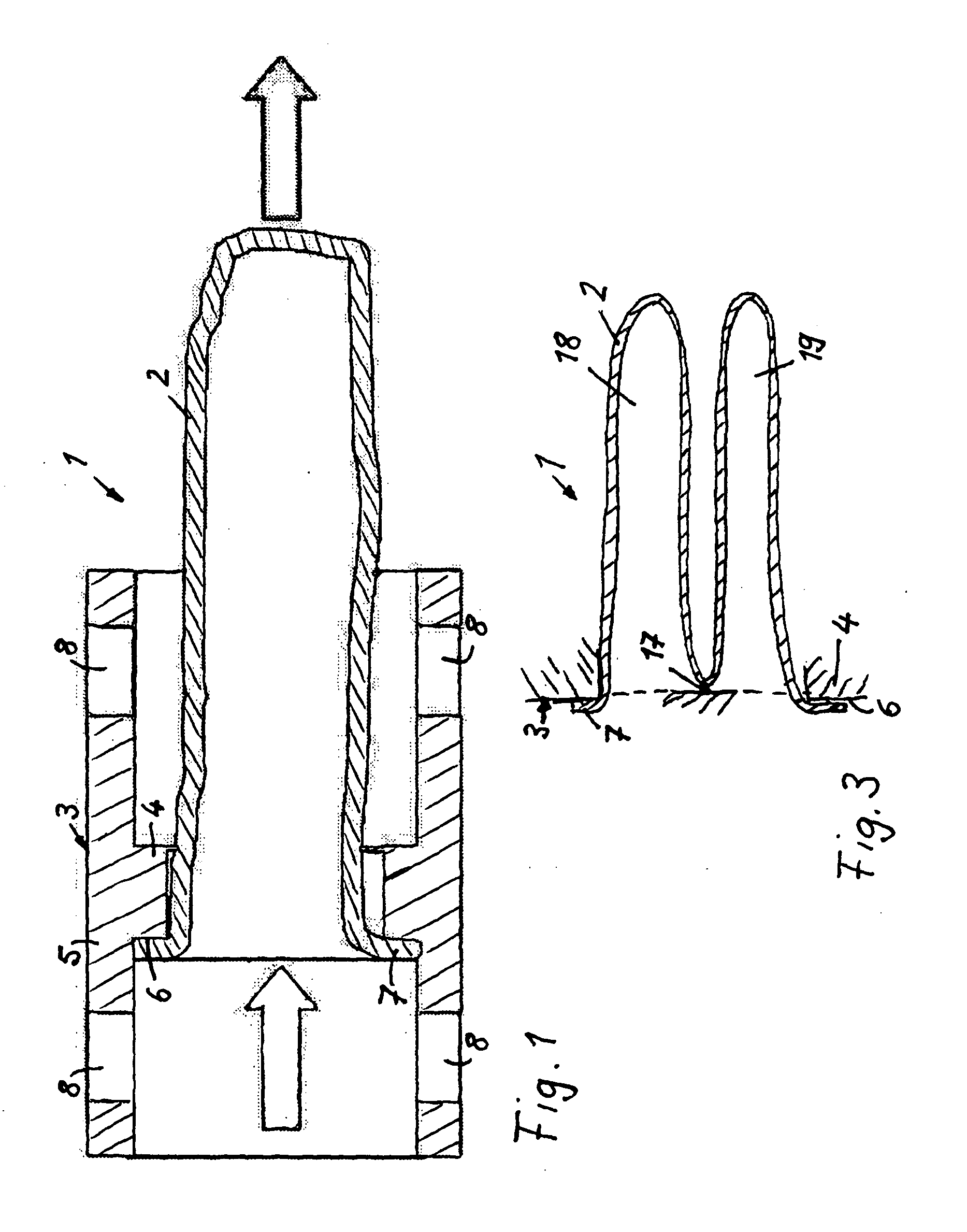
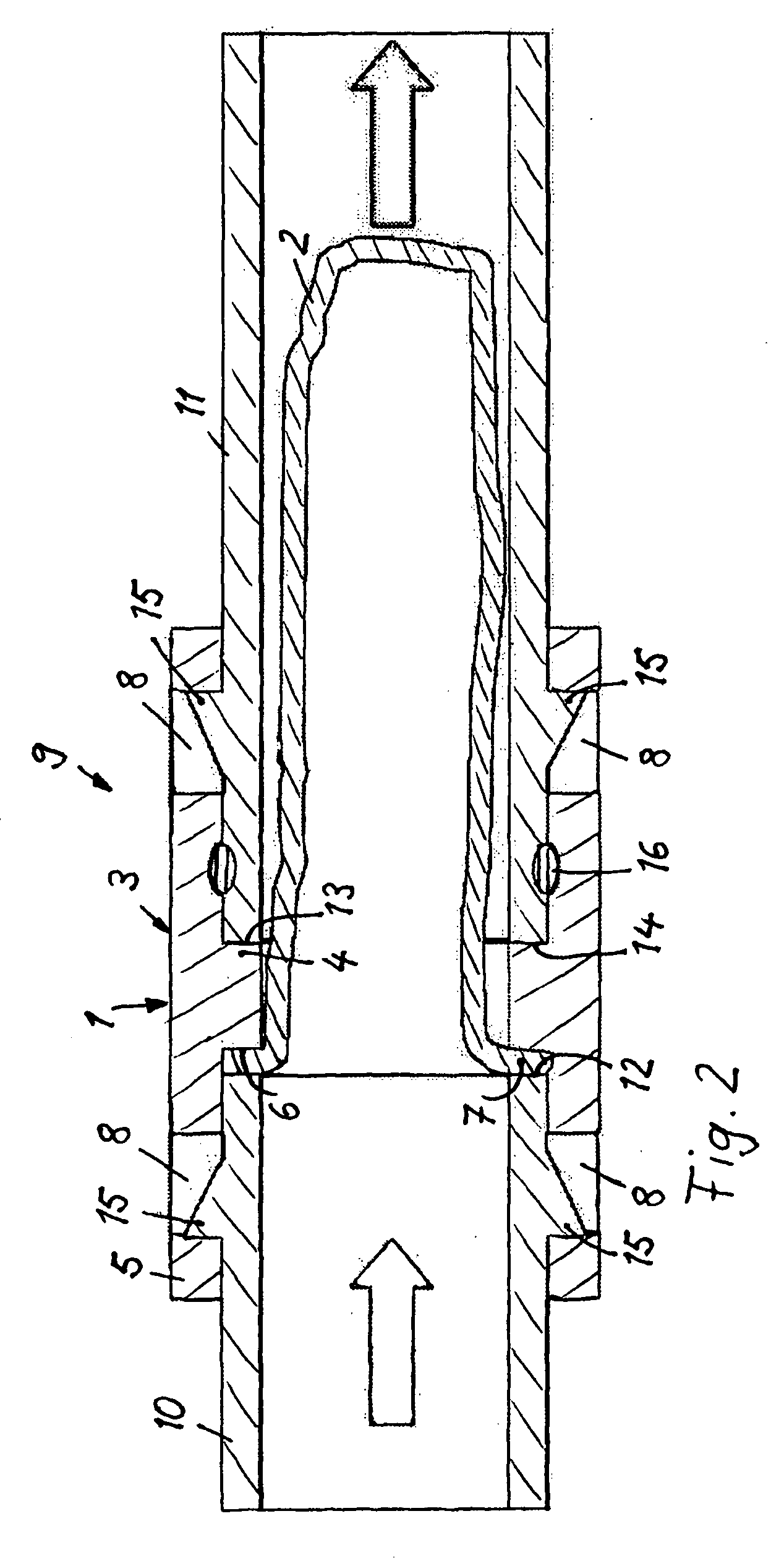
[0019]In FIG. 1, a filter module 1 is illustrated comprised of a hose-shaped filter element 2 of soft, yielding material and a support part 3 that is configured as the sleeve or a tubular member and to which is secured the filter element 2 in a safe and optionally also detachable way. Filter element 2 and support part 3 form a mating unit that is premanufactured outside of its location of use and is installed as a modular unit 1. The filter module 1 is used in particular for filtration of combustion air in internal combustion engines. The flow direction of the fluid to be purified is in the axial direction as indicated by the illustrated arrows. The flow direction can also be in the opposite direction, i.e., in the direction opposite to the illustrated arrows, so that the wall of the hose-shaped filter element can also be flown through from the exterior to the interior.

[0020]The support part 3 is comprised of a radially inwardly positioned annular fastening projection 4, wherein the...


PUM

PropertyMeasurementUnit
Flow rateaaaaaaaaaa

Abstract

The invention relates to a filtering device, comprising a tubular filter element and a carrier part, with the filter element fastened thereon. The carrier part can be inserted between an unfiltered fluid pipe and a filtered fluid pipe. The pipes can be assembled into a continuous flow pipe, wherein the filter element protrudes into the pipe interior.

Description

TECHNICAL FIELD[0001]The invention concerns a filtering device, in particular for the filtration of combustion air in internal combustion engines, according to the preamble of claim 1.PRIOR ART[0002]EP 0 450 299 A1 discloses a filtering device for the filtration of combustion air in internal combustion engines that comprises a zigzag-shaped folded filter element arranged in a plate shape in a filter housing. The filtering device is arranged in the intake manifold of the internal combustion engine wherein the combustion air to be purified is supplied through pipe conduits to the unfiltered side of the filter element, is filtered upon passing through the filter element, and is subsequently discharged through the filtered side of the filter element and further pipe sections and supplied to the cylinder inlets of the internal combustion engine.[0003]The filtration of the combustion air is very important for proper functioning of the internal combustion engine as well as the auxiliaries ...

Claims


Application Information

Patent Timeline
IPC IPC(8): B01D53/00
CPCB01D46/0012B01D2279/60B01D2265/028B01D46/02
Inventor JESSBERGER, THOMASHANSELMANN, MARKUSSCHOLL, HANS-PETERWALTENBERG, KLAUSWALZ, STEFANEISENGRAEBER-PABST, JOBSTPELZ, ANDREASLAMPERT, JOHANNESTHIENEL, MICHAELKNODEL, DANIELASTREICH, JOACHIMBAUER, SASCHA
Owner MANN HUMMEL GMBH
Why Eureka
Try Eureka