Combustor structure

a combustor and turbomachine technology, applied in the direction of machines/engines, stators, lighting and heating apparatus, etc., can solve the problems of gas turbine operability problems, combustor dynamics, variable and oscillating,

Inactive Publication Date: 2010-01-14
GENERAL ELECTRIC CO
View PDF15 Cites 38 Cited by
  • Summary
  • Abstract
  • Description
  • Claims
  • Application Information

AI Technical Summary

Benefits of technology

[0004]According to one aspect of the invention, a combustor includes at least one combustor liner defining a combustion chamber capable of directing combustion products toward a turbine. At least one combustor sleeve is located outside of the combustion chamber and is capable of reducing a magnitude of acoustic waves in the combustion chamber. The at least one combustor liner and the at least one combustor sleeve define at least one flow channel therebetween.

Problems solved by technology

This acoustic phenomena leads to variations and oscillations of pressure and temperature in the air provided to the combustor and subsequently gas turbine operability issues such as combustor lean blow out, combustor dynamics, increased emissions, and other gas turbine operability issues.
Further, these approaches are post mortem, being applied only after an issue is discovered through testing and / or operation of the gas turbine.

Method used


Image

  • Combustor structure
  • Combustor structure
  • Combustor structure

Examples


Embodiment Construction

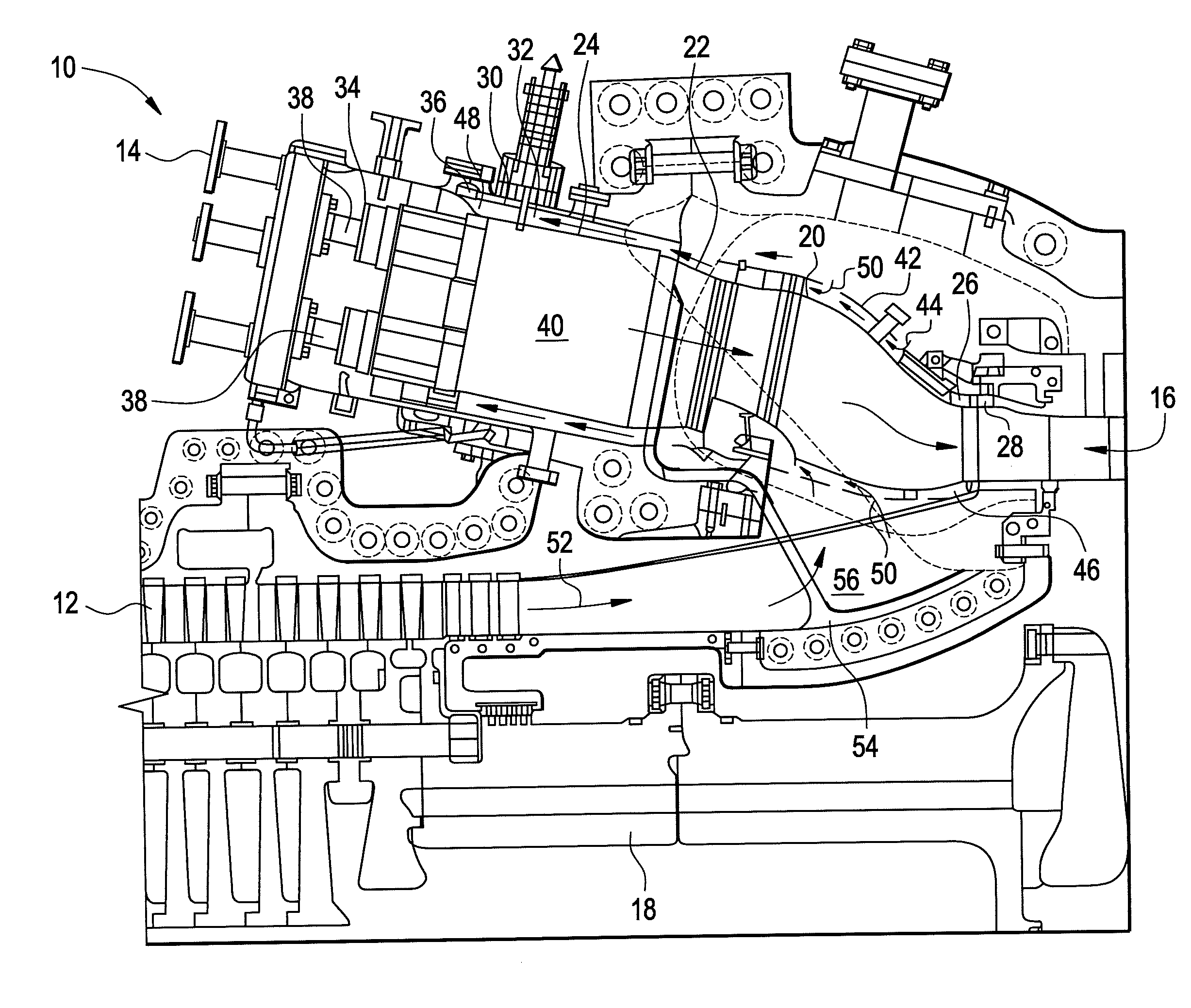
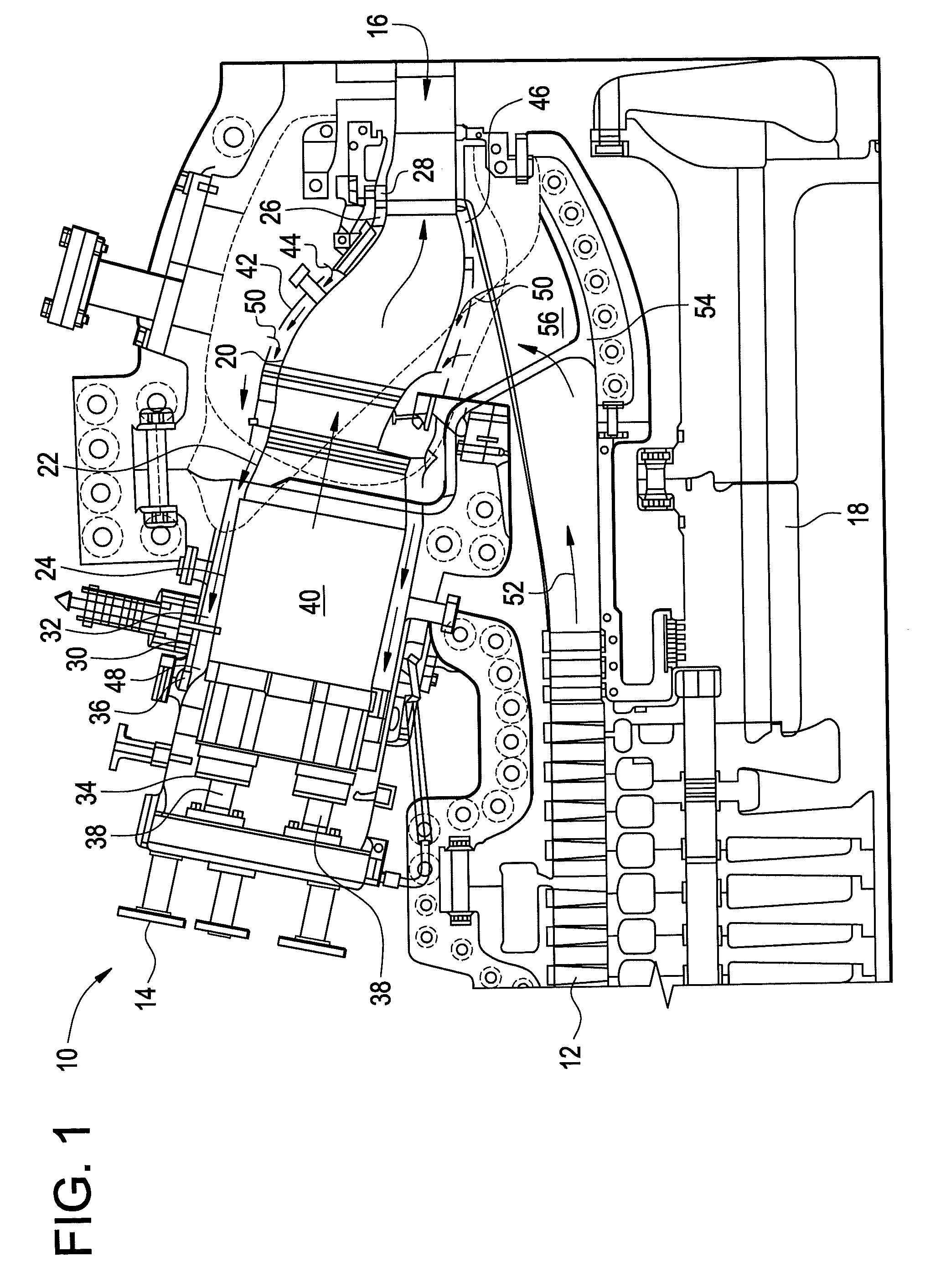
[0013]Shown in FIG. 1 is a turbomachine, for example, a gas turbine 10. The gas turbine 10 includes a compressor 12 which provides compressed fluid to a plurality of combustors 14. Fuel is injected into the combustor 14, mixes with the compressed air and is ignited. The hot gas product of the combustion flows to a turbine 16 which extracts work from the hot gas to drive a rotor shaft 18 which in turn drives the compressor 12. The plurality of combustors 14 may be arranged circumferentially around the rotor shaft 18, and in some embodiments may number 10 or 14 combustors 14. A transition piece 20 is coupled at an upstream end 22 to the combustor 14 at a combustor liner 24 and at a downstream end 26 to an aft frame 28 of the turbine 16. The transition piece 20 carries hot gas flow from the combustor liner 24 to the turbine 16. The combustor 14 includes a combustor sleeve 30 spaced radially outward from the combustor liner 24 defining a combustor flow channel 32 therebetween. A combust...


PUM


Abstract

A combustor includes at least one combustor liner defining a combustion chamber capable of directing combustion products toward a turbine. At least one combustor sleeve is located outside of the combustion chamber and is capable of reducing a magnitude of acoustic waves in the combustion chamber. The at least one combustor liner and the at least one combustor sleeve define at least one flow channel therebetween. Further, a combustor includes at least one combustor liner defining a combustion chamber capable of directing combustion products toward turbomachinery. At least one combustor sleeve disposed outside of the combustion chamber and is capable of controlling distribution of fluid flow in the combustor to modify a uniformity of the fluid flow to the combustion chamber.

Description

BACKGROUND[0001]The subject invention relates to turbomachinery. More particularly the subject invention relates to combustor construction for a turbomachine.[0002]In a typical turbomachine, for example, a gas turbine, a combustor converts chemical energy of a fuel or a fuel and air mixture into thermal energy. The thermal energy is conveyed by a fluid, often air from a compressor, to a turbine where the thermal energy is converted into mechanical energy. Many characteristics of the gas turbine impact the efficiency of these energy conversions. The characteristics include blade passing frequencies, fuel supply fluctuations, combustor head-on volume, fuel nozzle design, fuel air profiles, purge airflow, flame shape and flame stabilization. One example is a vibratory or acoustic frequency, blade passing frequency (BPF), produced at the exit of the compressor by a row of blades passing a row of stationary vanes at the compressor exit. This acoustic phenomena leads to variations and osc...

Claims


Application Information

Patent Timeline
Patent Type & Authority Applications(United States)
IPC IPC(8): F02C1/00
CPCF01D9/023F23R3/002F23R2900/03044F23R2900/00014F23R3/16
Inventor CHEN, WEIJOHNSON, DAVID MARTINCHILA, RONALD JAMESCITENO, JOSEPH
Owner GENERAL ELECTRIC CO
Why Eureka
Try Eureka