Cover lens with touch sensing function

a technology of touch sensing and cover lens, which is applied in the field of cover lens, can solve the problems of damage to plate permittivity, and easy failure of touch panel during manufacturing process, so as to facilitate installation, and reduce the thickness of the assembled pla

Inactive Publication Date: 2010-01-14
YOUNG FAST OPTOELECTRONICS
View PDF4 Cites 68 Cited by
  • Summary
  • Abstract
  • Description
  • Claims
  • Application Information

AI Technical Summary

Benefits of technology

[0003]Accordingly, the primary object of the present invention is to provide a cover lens with touch sensing function. On a bottom surface of the cover lens, a touch sensing structure is formed so that the layers and the thickness of the assembled plate are reduced and the high permittivity and the convenience of installation are maintained. Moreover, the combination of the cover lens and the touch panel can simplify the manufacturing process and also reduce the production cost and raise the production yield.

Problems solved by technology

However, an assembled plate with a thickness over 1.5 mm will cause a structure and appearance design problem, and will also seriously damage the permittivity of the plate.
Issues of fuzzy image and gloomy color are occurred.
Thus a thinner touch panel is requested and because of the requested thin glass substrate and the thin sensing films, the touch panel is easily failed during the manufacturing processes.
The quality of the touch panel is damaged and the production cost is highly raised.

Method used


Image

  • Cover lens with touch sensing function
  • Cover lens with touch sensing function
  • Cover lens with touch sensing function

Examples


Embodiment Construction

[0010]In order that those skilled in the art can further understand the present invention, a description will be provided in the following in details. However, these descriptions and the appended drawings are only used to cause those skilled in the art to understand the objects, features, and characteristics of the present invention, but not to be used to confine the scope and spirit of the present invention defined in the appended claims.

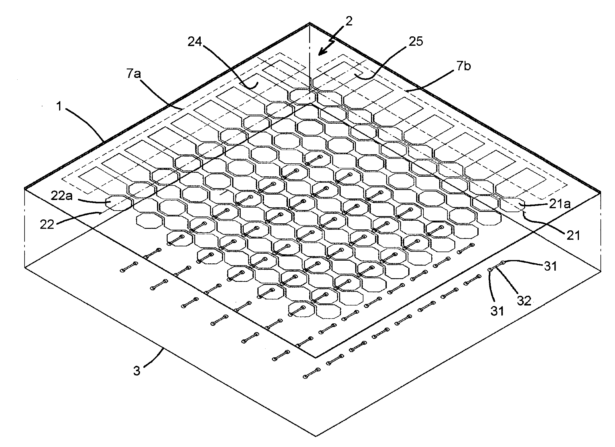
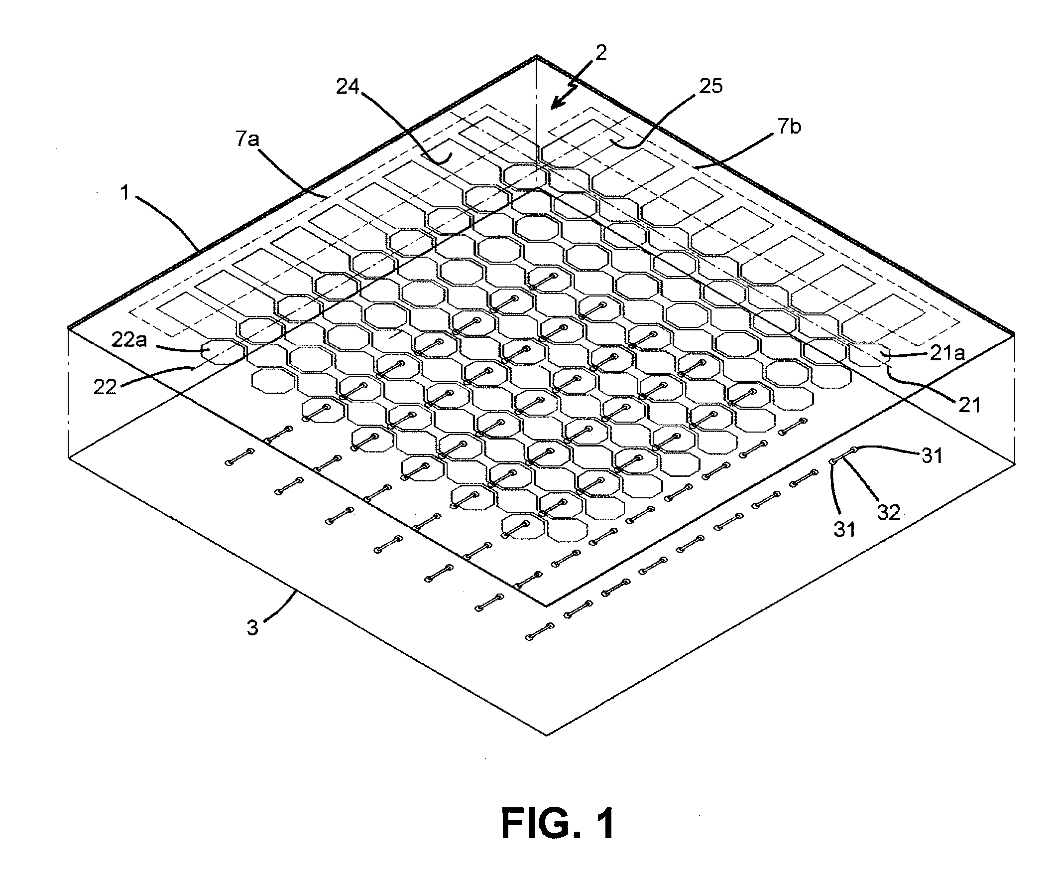
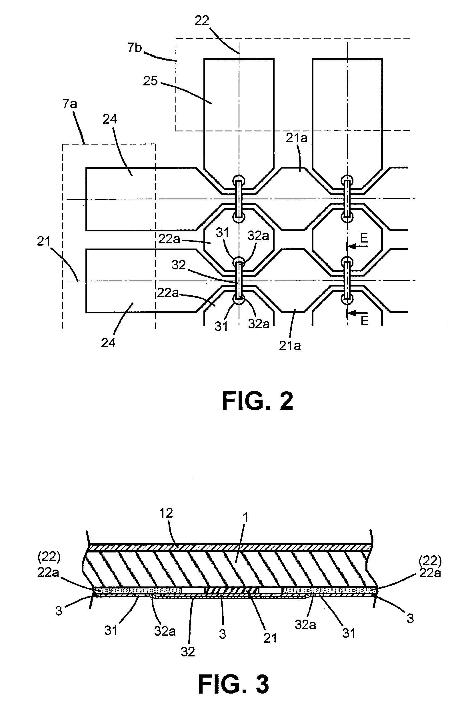
[0011]Referring to FIGS. 1 to 3, a preferable embodiment of the present invention is illustrated. The present invention mainly includes a substrate, a surface layer, a sensing layer, and an insulated layer.

[0012]The substrate 1 of the cover lens is made of a 0.5 mm polymethylmethacrylate (PMMA) thin plate with permittivity of 95%. A surface layer 12 arranged on an upper surface of the substrate 1 is a hard coat layer with thickness of less than 0.1 mm.

[0013]The sensing layer 2 is made of a clear conductive film of Indium Tin Oxide. The sensing laye...


PUM


Abstract

A cover lens with touch sensing function is a transparent plate formed by a substrate, a surface layer, a sensing layer, and an insulated layer. The substrate of the cover lens is a highly transparent plate with outstanding mechanical strength. The surface layer consists of one or a plurality of functional films and is arranged on an upper surface of the substrate. The sensing layer is arranged on a bottom surface of the substrate and further has a plurality of X axis traces and Y axis traces. The X and Y axis traces are formed on the same plane and intersect to each other as a matrix. Induction-spots are formed on each X axis trace and are connected one by one. Induction-spots are formed on each Y axis trace but are formed separately with gaps. Pairs of through holes is formed respectively to all the adjacent induction-spots of each Y axis trace on the insulated layer. A conductive wire crossing between the pair of the through holes is arranged on the surface of the insulated layer. Both ends of the conductive wire exposed to the through holes respectively are formed as electrical joints. The insulated layer is covered on the sensing layer from a bottom surface so as to cover and insulate the X and Y axis traces.

Description

FIELD OF THE PRESENT INVENTION[0001]The present invention relates to cover lens, and in particular to a cover lens with touch sensing function.DESCRIPTION OF THE PRIOR ART[0002]A lot of electronic products such as cell phone, camera, PDA, laptop will be arranged with a cover lens before the Liquid Crystal Display (LCD) equipped on it for the purpose of protecting the screen from being scratched or polluted. Otherwise, for improving the convenience of the input operation, touch panels are widely used with the screen of the electronic products. In practice, the touch panel stacking the cover lens is a most common application used on a screen of the electronic products. For example of a cell phone, the cover lens is usually a transparent thin plate with certain mechanical strength and with thickness about 0.8 to 1.0 mm. On an upper surface of the cover lens, a plurality of functional films will be arranged such as a polarization film, filter film, and scratch-proof film. The thickness ...

Claims


Application Information

Patent Timeline
Patent Type & Authority Applications(United States)
IPC IPC(8): G06F3/041
CPCG02F1/133526G06F2203/04111G06F3/044G02F2201/503G06F3/0446
Inventor YANG, KAI-TI
Owner YOUNG FAST OPTOELECTRONICS
Why Eureka
Try Eureka