Lc composite component

a composite component and capacitor technology, applied in the direction of impedence networks, electrical devices, multiple-port networks, etc., can solve the problems of inability to obtain coupling as strong as that obtained by arranging the coil electrodes to touch each other, undetectable surface-direction size of a multi-layer substrate, etc., to achieve the effect of increasing coupling flexibility and reducing the siz

Active Publication Date: 2010-01-14
MURATA MFG CO LTD
View PDF10 Cites 8 Cited by
  • Summary
  • Abstract
  • Description
  • Claims
  • Application Information

AI Technical Summary

Benefits of technology

[0010]Preferred embodiments of the present invention provide an LC composite component capable of reducing the entire size while keeping a Q-value of resonators at a high level and increasing coupling flexibility between resonators.

Problems solved by technology

However, since two coil electrodes are arranged side by side in a bandpass filter disclosed in Japanese Unexamined Patent Application Publication No. 6-244605, the surface-direction size of a multilayer substrate undesirably increase.
In addition, since the coil electrodes are arranged side by side in the horizontal direction, coupling as strong as that obtained by arranging the coil electrodes to touch each other may not be obtained although the coupling therebetween can be increased by decreasing the horizontal distance therebetween.

Method used


Image

  • Lc composite component
  • Lc composite component
  • Lc composite component

Examples


first preferred embodiment

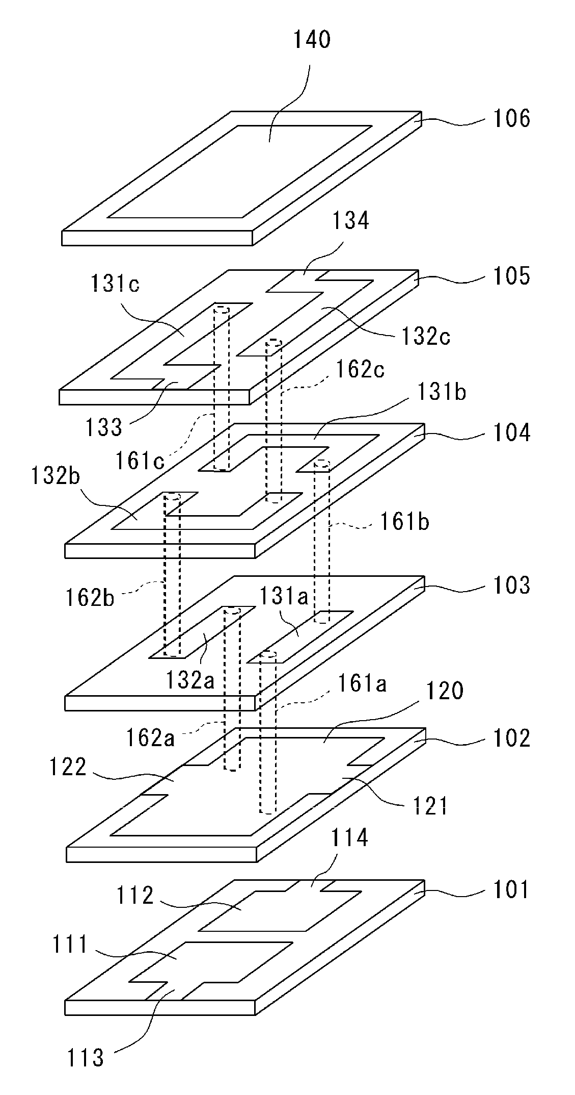
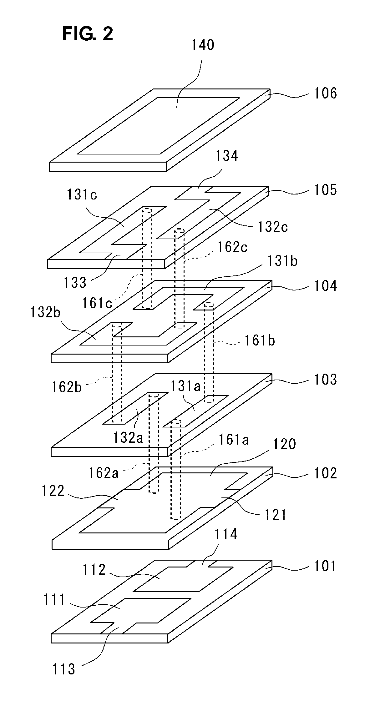
[0046]A multilayer bandpass filter according to a first preferred embodiment will be described with reference to FIGS. 2-5.

[0047]FIG. 2 is an exploded perspective view of a multilayer bandpass filter according to the first preferred embodiment, whereas FIG. 3 is a perspective view thereof.

[0048]A multilayer bandpass filter 1 according to the first preferred embodiment includes a plurality of laminated dielectric layers 101-106 having various electrode patterns provided thereon. For example, the size of the multilayer bandpass filter 1 shown in FIG. 3 preferably is substantially 1.0 mm×0.5 mm and the height thereof is substantially 0.4 mm.

[0049]Each of the dielectric layers 101-106 is a dielectric sheet formed of LTCC (low temperature co-fired ceramics that is formed of a glass component and at least one of components, such as, for example, titanium oxide, barium oxide, and alumina) having a relative dielectric constant εr=53.5, for example.

[0050]As shown in FIG. 3, ground terminals ...

second preferred embodiment

[0076]FIG. 6 is an exploded perspective view of a multilayer bandpass filter according to a second preferred embodiment. A difference from the multilayer bandpass filter according to the first preferred embodiment shown in FIG. 2 is that the multilayer bandpass filter according to the second preferred embodiment further includes a dielectric layer 107.

[0077]Capacitor electrodes 151 and 152 and input / output terminal electrodes 153 and 154 extending from the capacitor electrodes 151 and 152, respectively, are provided on the dielectric layer 107.

[0078]Capacitance is generated between the capacitor electrodes 151 and 152 and the capacitor electrode 140 provided on the dielectric layer 106. The input / output terminal electrodes 153 and 154 as well as the input / output terminal electrodes 113 and 114 provided on the dielectric layer 101 are connected to the input / output terminals 12 and 13 shown in FIG. 3, respectively. Accordingly, capacitance generated between the capacitor electrodes 15...

third preferred embodiment

[0079]FIG. 7 is an exploded perspective view of a multilayer bandpass filter according to a third preferred embodiment. A difference from the configuration of the multilayer bandpass filter shown in FIG. 6 is that the multilayer bandpass filter according to the third preferred embodiment further includes a dielectric layer 100.

[0080]A ground electrode 170 and ground terminal electrodes 171 and 172 extending from the ground electrode 170 are provided on the dielectric layer 100.

[0081]The ground terminal electrodes 171 and 172 of the ground electrode 170 as well as the ground terminal electrodes 121 and 122 provided on the dielectric layer 102 are connected to the ground terminals 11 and 11, respectively. Accordingly, capacitance is generated between the capacitor electrodes 111 and 112 and the ground electrodes 120 and 170. The capacitance corresponds to the capacitors C1 and C2 of the equivalent circuit shown in FIG. 5 and sets a resonant frequency of an LC resonator.

[0082]In partic...


PUM


Abstract

An LC composite component capable of reducing an overall size while keeping a Q-value of a resonator at a high level and increasing coupling flexibility of resonators includes two capacitor electrodes and two input/output terminal electrodes extending therefrom provided on a first dielectric layer. A ground electrode and another capacitor electrode are provided on second and sixth dielectric layers, respectively. Two substantially linear line electrodes are provided on a third dielectric layer. Two substantially U-shaped line electrodes are provided on a fourth dielectric layer. Two substantially crank-shaped line electrodes are provided on a fifth dielectric layer. Six via electrodes arranged to connect ends of respective line electrodes are provided on the third, fourth, and fifth dielectric layers. These via electrodes and line electrodes constitute electrodes of a double helix structure.

Description

BACKGROUND OF THE INVENTION[0001]1. Field of the Invention[0002]The present invention relates to an inductor-capacitor (LC) composite component, such as, for example, a bandpass filter, that includes an inductor and a capacitor in a multilayer body of a plurality of dielectric layers.[0003]2. Description of the Related Art[0004]Japanese Unexamined Patent Application Publication No. discloses a bandpass filter having helical coils in a dielectric multilayer body.[0005]A configuration of a multilayer bandpass filter disclosed in Japanese Unexamined Patent Application Publication No. 6-244605 will be described with reference to FIG. 1.[0006]Referring to FIG. 1, substantially U-shaped conductor patterns P are formed on a surface of a dielectric green sheet G by screen printing. There are two arrangement states of the conductor patterns P. One is a state where openings of the U-shape face each other, whereas the other is a state where sides of the U-shape, opposite to the opening, face e...

Claims


Application Information

Patent Timeline
Patent Type & Authority Applications(United States)
IPC IPC(8): H03H7/01
CPCH03H7/09H03H2001/0085H03H7/1775H03H7/1708
Inventor TANIGUCHI, TETSUO
Owner MURATA MFG CO LTD
Why Eureka
Try Eureka