
Methods and apparatus for efficient purging

a technology of purging and purging chamber, applied in the field of medical devices, can solve the problems of difficult manipulation, inability to provide therapeutic treatment for conventional catheter imaging systems, and difficulty in treating atrial fibrillation in patients' hearts, and achieve the effect of reducing the amount of saline discharg

Active Publication Date: 2010-01-14
INTUITIVE SURGICAL OPERATIONS INC
View PDF107 Cites 71 Cited by
  • Summary
  • Abstract
  • Description
  • Claims
  • Application Information

AI Technical Summary

Benefits of technology

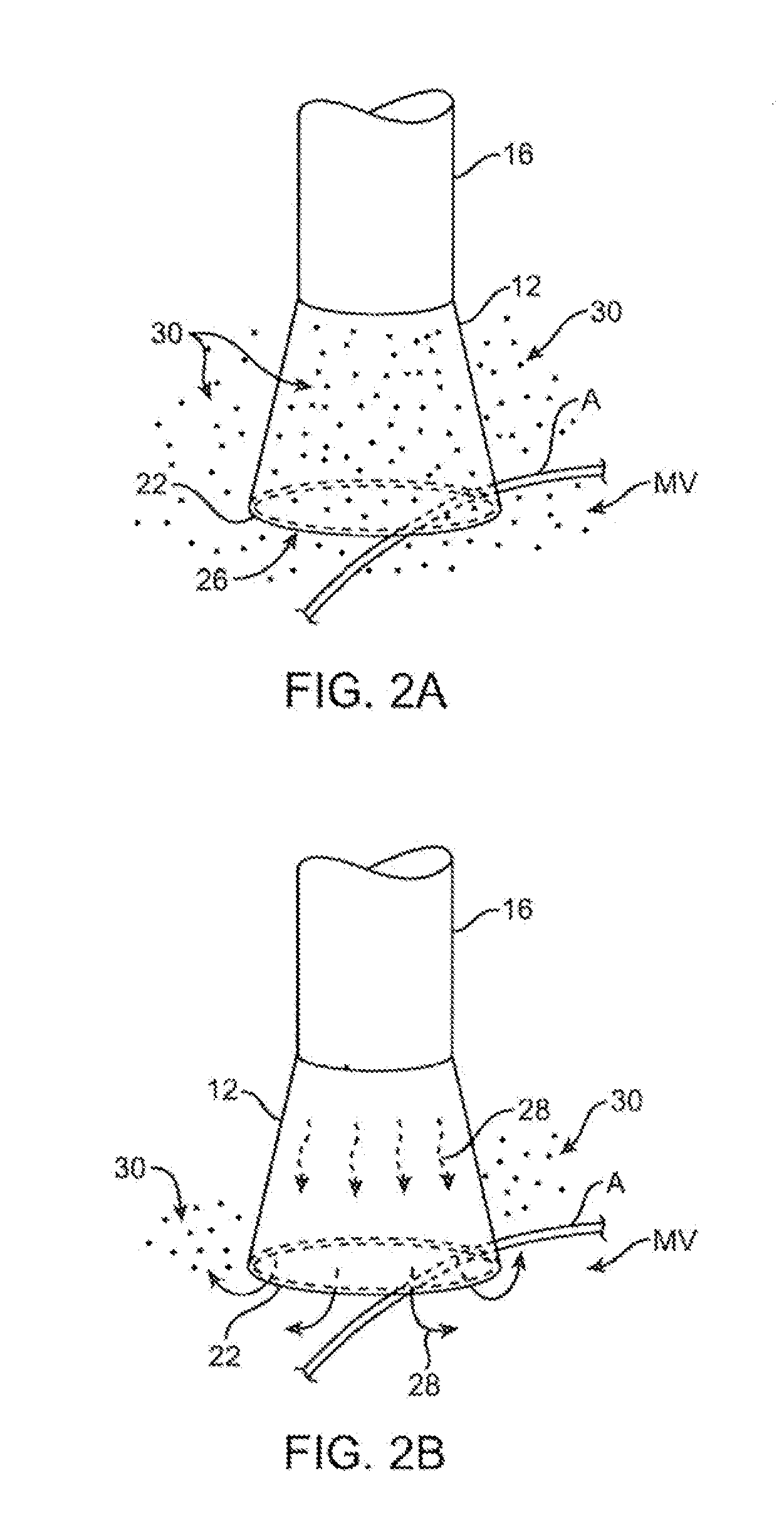
[0015]In clearing the hood of blood and / or other bodily fluids, it is generally desirable to purge the hood in an efficient manner by minimizing the amount of clearing fluid, such as saline, introduced into the hood and thus into the body. As excessive saline delivered into the blood stream of patients with poor ventricular function may increase the risk of heart failure and pulmonary edema, minimizing or controlling the amount of saline discharged during various therapies, such as atrial fibrillation ablation, atrial flutter ablation, transseptal puncture, etc. may be generally desirable.
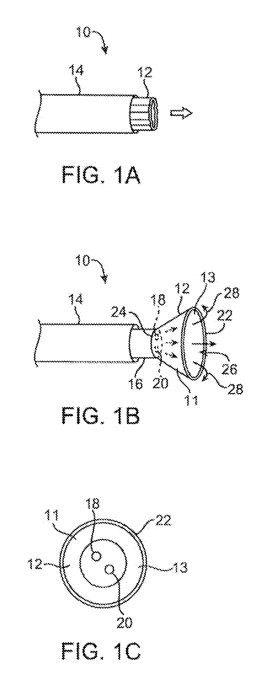
[0017]Flow of the saline fluid out of the hood through the main aperture may continue under relatively low fluid pressure conditions as saline is introduced from the catheter shaft, through the diaphragm apertures, and out of the main aperture. Upon the application of a relatively higher fluid pressure, the diaphragm may be pushed distally within the hood until it extends or bulges distally to block the main aperture until fluid flow out of the hood is reduced or completely stopped. With the aperture blocked, the hood may retain the purging fluid within to facilitate visualization through the fluid of the underlying tissue. Thus, the hood may be panned around a target tissue region with sustained visualization to reduce the amount of saline that is introduced into a patient's heart or bloodstream. Once the fluid pressure of the purging fluid is reduced, the diaphragm may retract to unblock the aperture and thus allow for the flow of the purging fluid again through the diaphragm apertures and main aperture. Alternatively, one or more unidirectional valves may be positioned over the diaphragm to control the flow of the purging fluid through the hood and out the main aperture. Other variations may incorporate an internal inflation member or pouch which may be positioned within the hood and which controls the outflow of the purged saline based on the fluid pressure within the pouch.
[0020]Another variation of the hood may incorporate one or more protrusions or projections extending from a distal membrane over the hood. These protrusions or projections may extend distally adjacent to a corresponding unidirectional valve which has overlapping leaflets. As the hood is filled with the purging fluid, flow through the valves is inhibited or prevented by the overlapping leaflets but as the distal face of the hood membrane is pressed against a surface of tissue to be visualized and / or treated, the protrusions or projections pressing against the tissue surface may force the valve leaflets to separate temporarily, thus allowing the passage of saline out through the valves to clear any blood within the hood as well as any blood between membrane and the tissue surface.
[0021]In yet another variation, an imaging hood may be configured to form a recirculating flow inside the hood. The purging fluid may be introduced (e.g., injected) as well as withdrawn from the imaging hood interior through two different lumens in the catheter shaft. For instance, the fluid may be introduced by an inlet lumen which injects the fluid along a first path into the hood while the recirculating fluid may be withdrawn by suction through a separate outlet lumen. By keeping a relatively higher volume flow rate in the inlet lumen for injecting the purging fluid than the flow rate in the outlet lumen for withdrawing it, a considerable amount of purging fluid may be conserved resulting in efficient hood purging. Another variation may incorporate a suction lumen, e.g., a pre-bent lumen, extending from the catheter directly to the main aperture. This particular variation may allow for the direct evacuation of blood through a lumen opening at a particular location along the main aperture where the in-flow of blood (or other opaque fluids) is particularly high.
[0024]In yet another variation, an imaging hood may have a distal membrane without an aperture and which may be filled with the purging fluid once desirably positioned within the subject's body in proximity to the tissue region to be visualized and / or treated. Once a tissue region to be treated has been located by the hood, a piercing instrument may be advanced through the hood from the catheter to puncture through the distal membrane at a desired site. This may form a puncture aperture through which the purging fluid may escape. Hence, purging is only performed at locations where instruments are passed out of the imaging hood thus reducing the amount of saline discharged out of the hood.

Problems solved by technology

However, many of the conventional catheter imaging systems lack the capability to provide therapeutic treatments or are difficult to manipulate in providing effective therapies.
For instance, the treatment in a patient's heart for atrial fibrillation is generally made difficult by a number of factors, such as visualization of the target tissue, access to the target tissue, and instrument articulation and management, amongst others.
Conventional catheter techniques and devices, for example such as those described in U.S. Pat. Nos. 5,895,417; 5,941,845; and 6,129,724, used on the epicardial surface of the heart may be difficult in assuring a transmural lesion or complete blockage of electrical signals.
In addition, current devices may have difficulty dealing with varying thickness of tissue through which a transmural lesion is desired.
Conventional accompanying imaging devices, such as fluoroscopy, are unable to detect perpendicular electrode orientation, catheter movement during the cardiac cycle, and image catheter position throughout lesion formation.
The absence of real-time visualization also poses the risk of incorrect placement and ablation of structures such as sinus node tissue which can lead to fatal consequences.

Method used


Image

  • Methods and apparatus for efficient purging
  • Methods and apparatus for efficient purging
  • Methods and apparatus for efficient purging

Examples


Embodiment Construction

[0045]A tissue-imaging and manipulation apparatus described herein is able to provide real-time images in vivo of tissue regions within a body lumen such as a heart, which is filled with blood flowing dynamically therethrough and is also able to provide intravascular tools and instruments for performing various procedures upon the imaged tissue regions. Such an apparatus may be utilized for many procedures, e.g., facilitating transseptal access to the left atrium, cannulating the coronary sinus, diagnosis of valve regurgitation / stenosis, valvuloplasty, atrial appendage closure, arrhythmogenic focus ablation, among other procedures.

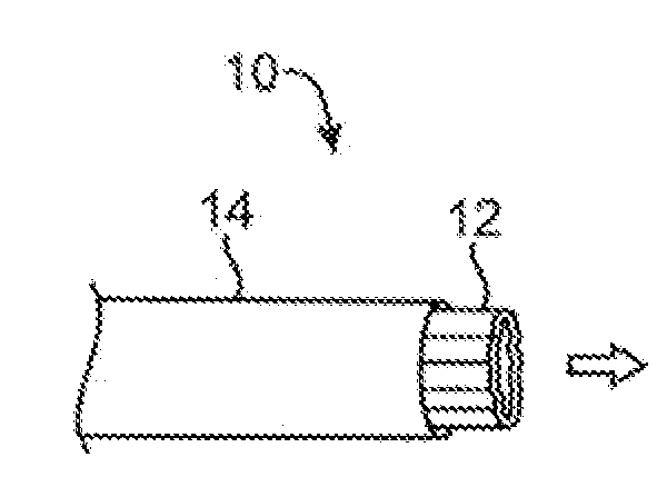
[0046]One variation of a tissue access and imaging apparatus is shown in the detail perspective views of FIGS. 1A to 1C. As shown in FIG. 1A, tissue imaging and manipulation assembly 10 may be delivered intravascularly through the patient's body in a low-profile configuration via a delivery catheter or sheath 14. In the case of treating tissue, it is gener...


PUM


Abstract

Methods and apparatus for efficient purging from an imaging hood are described which facilitate the visualization of tissue regions through a clear fluid. Such a system may include an imaging hood having one or more layers covering the distal opening and defines one or more apertures which control the infusion and controlled retention of the clearing fluid into the hood. In this manner, the amount of clearing fluid may be limited and the clarity of the imaging of the underlying tissue through the fluid within the hood may be maintained for relatively longer periods of time by inhibiting, delaying, or preventing the infusion of surrounding blood into the viewing field. The aperture size may be controlled to decrease or increase through selective inflation of the membrane or other mechanisms.

Description

CROSS-REFERENCE TO RELATED APPLICATIONS[0001]This application claims the benefit of priority to U.S. Prov. Pat. App. 61 / 079,414 filed Jul. 9, 2008, which is incorporated herein by reference in its entirety.FIELD OF THE INVENTION[0002]The present invention relates generally to medical devices used for accessing, visualizing, and / or treating regions of tissue within a body. More particularly, the present invention relates to methods and apparatus for efficiently purging opaque fluids from an intravascular visualization system to facilitate visualization and / or treatment of the tissue.BACKGROUND OF THE INVENTION[0003]Conventional devices for accessing and visualizing interior regions of a body lumen are known. For example, various catheter devices are typically advanced within a patient's body, e.g., intravascularly, and advanced into a desirable position within the body. Other conventional methods have utilized catheters or probes having position sensors deployed within the body lumen...

Claims


Application Information

Patent Timeline
Patent Type & Authority Applications(United States)
IPC IPC(8): A61B1/12A61B1/06
CPCA61B1/0008A61B1/00165A61B1/00089A61B1/00082A61B1/051A61B1/126
Inventor MILLER, DAVIDSAADAT, VAHIDMALCHANO, ZACHARY J.PEH, RUEY-FENGTHAKUR, ASEEM K.ROTHE, CHRIS A.TAM, EDMUND
Owner INTUITIVE SURGICAL OPERATIONS INC
Learn More