NGL Recovery Methods and Configurations

a technology of ethane recovery and configuration, applied in the field of gas processing, can solve the problems of inability to achieve high ethane recovery in excess of 90%, inconvenient operation, and inability to perform extra refrigeration, etc., and achieve the effect of high recovery

Inactive Publication Date: 2010-01-21
FLUOR TECH CORP
View PDF23 Cites 31 Cited by
  • Summary
  • Abstract
  • Description
  • Claims
  • Application Information

AI Technical Summary

Problems solved by technology

However, and especially where feed gas pressure is relatively low or contains significant quantities of propane and / or heavier components, extra refrigeration (e.g., propane refrigeration) may also be required.
These configurations are often used for feed gas with low CO2 (e.g., less than 2%) and relatively high C3+ (e.g., greater than 5%) content, and are generally not practical nor economically viable for feed gas with high CO2 content (greater than 2%) and low C3 + content (less than 2%, and more typically less than 1%).
However, even with significantly lowered temperatures in commonly known plants, high ethane recovery in excess of 90% is often not achievable due to CO2 freezing in the demethanizer.
Moreover, such operation is also typically economically not justifiable due to the high capital cost of the compression equipment and energy costs.
Thus, based on most known configurations, ethane recovery is typically limited to the 70% to 80% range due to CO2 freezing problems and economic constraints.
Unfortunately, while high propane recovery can be achieved with such a process, ethane recovery is often moderate (typically at about 70% to 80%).
Although high ethane recovery can be achieved with such a process, the cost of additional equipment such as additional compressors, separators, and heat exchangers is usually difficult to justify.
However, due to the very low temperatures, the methane content in the tray liquid is also very high, which invariably causes significant internal recycle of the methane component in the lower section.
Consequently, such configurations are inefficient as they require high reboiler duties and refrigeration requirements.
Moreover, due to the relatively low temperatures in the lower section, CO2 freezing is frequently encountered, which presents a significant obstacle for continuous operation.
Alternatively, CO2 concentration must be reduced in the feed gas to a tolerable limit, which typically adds significant expense.
However, all or almost all of them fail to achieve economic operation for high ethane recovery.

Method used


Image

  • NGL Recovery Methods and Configurations
  • NGL Recovery Methods and Configurations
  • NGL Recovery Methods and Configurations

Examples


Embodiment Construction

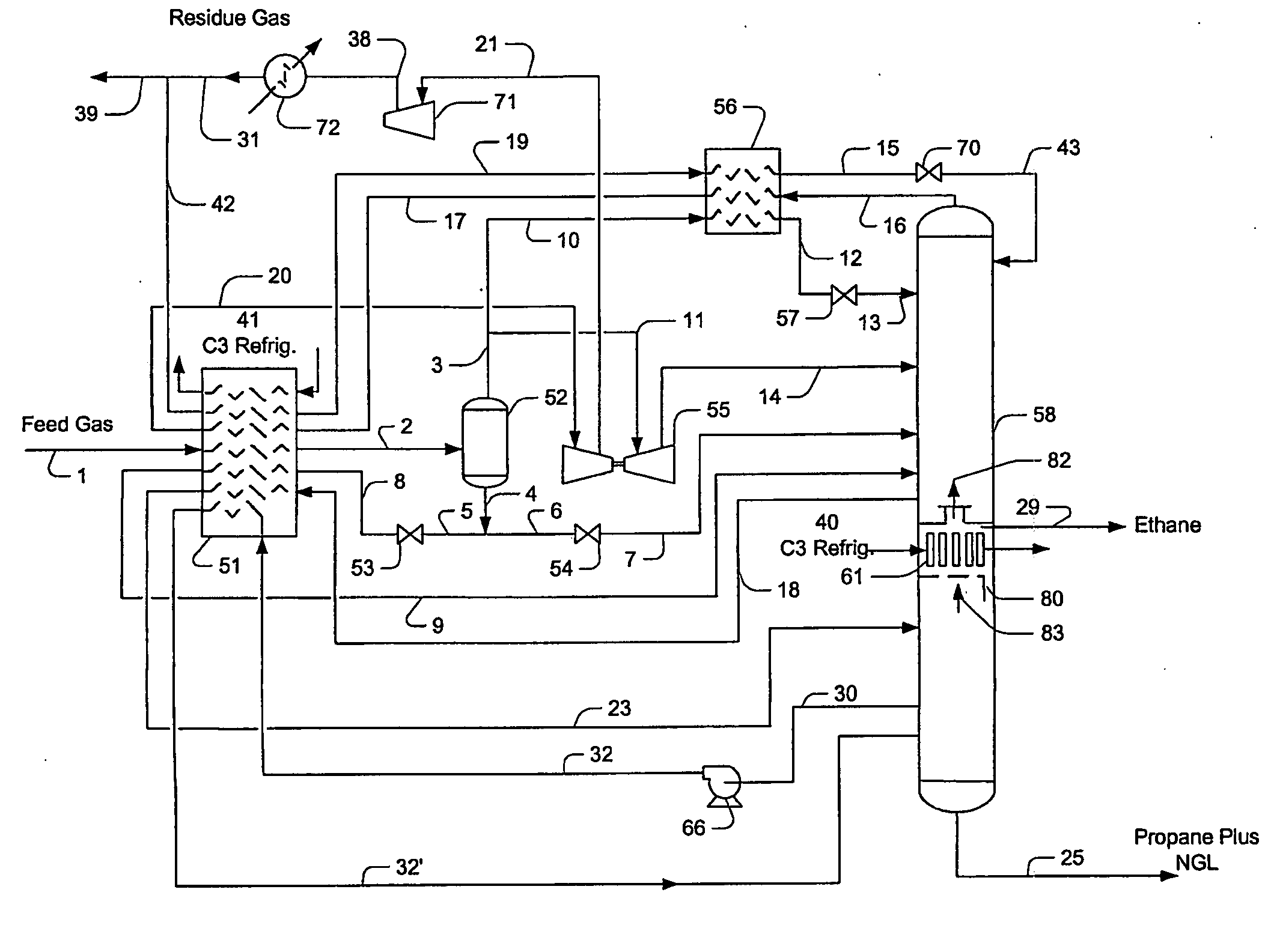
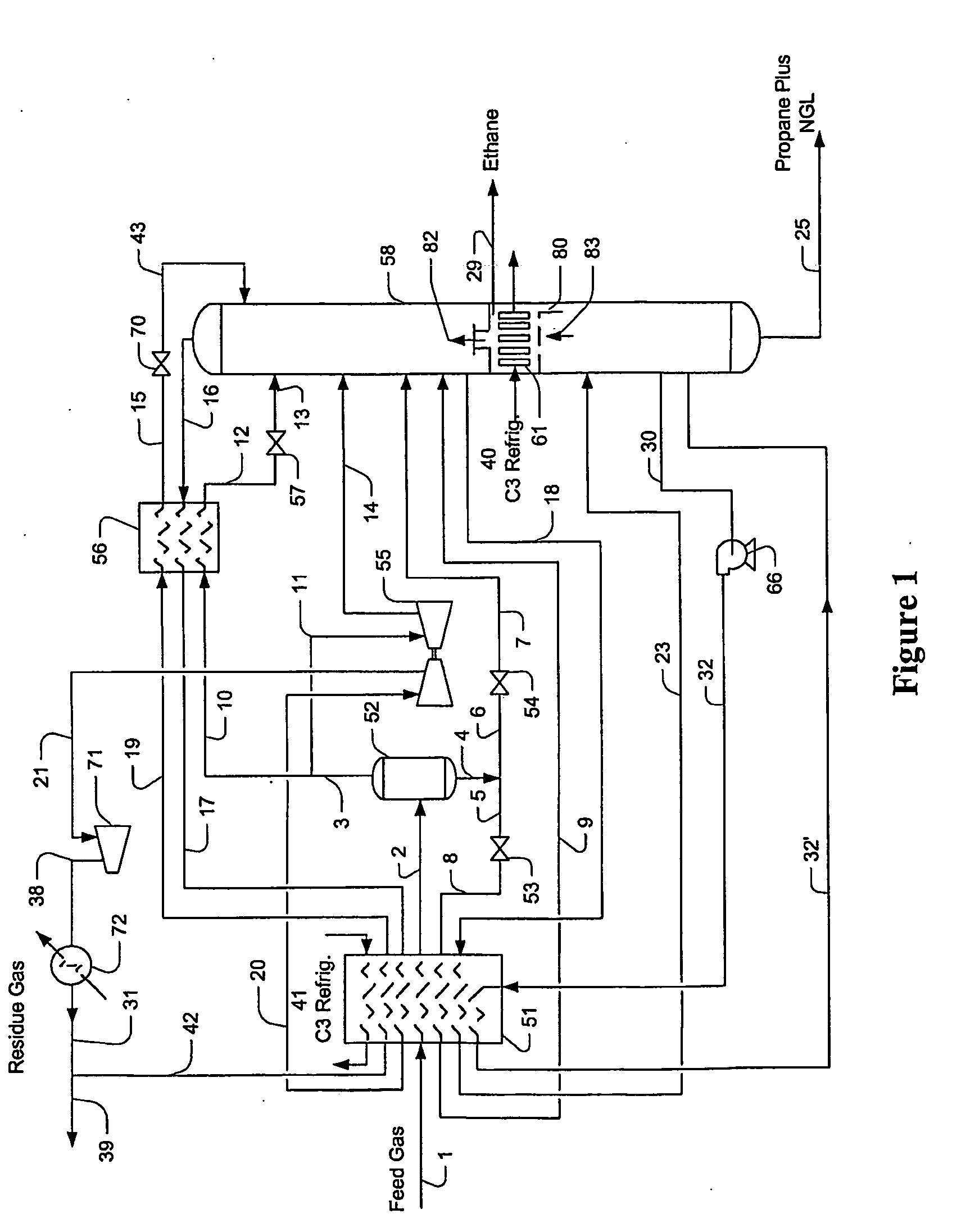
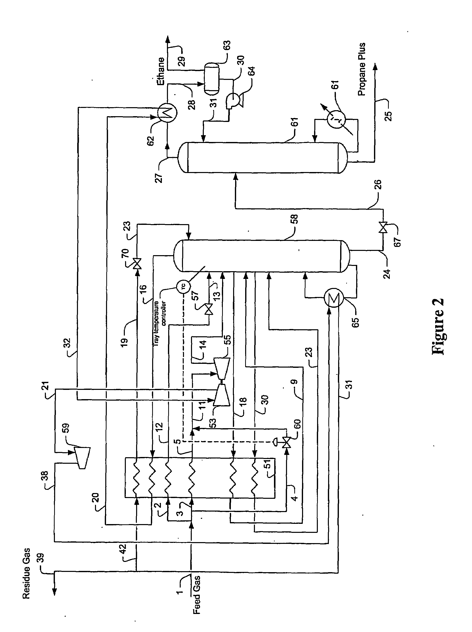
[0026]The inventors have discovered that flexible and high ethane and / or propane recovery (e.g., at least about 90% C2 and at least about 99% C3) can be achieved for a feed gas with relatively high CO2 content (greater than 2%) using optimum temperature control in the separation column(s). In most configurations, optimum temperature control is achieved with an intermediate reflux condenser in a single-column configuration or by control of the expander discharge in a dual-column configuration. Such temperature control advantageously reduces, if not even entirely eliminates carbon dioxide freezing in the column. Most typically, the fractionator in contemplated configurations will receive at least two lean reflux streams.

[0027]In a particularly preferred configuration as illustrated in FIG. 1, an exemplary plant includes a fractionation column 58 that is fluidly coupled to an intermediate reflux condenser 61 that is used to provide cooling to a lower rectification section. It should be...


PUM


Abstract

Contemplated plants and methods for NGL recovery from feed gases having a carbon dioxide content equal or greater than about 2% employ temperature control configurations that allow high-level and flexible recovery of ethane and heavier components while avoiding freezing of the carbon dioxide in the process. Where the feed gas has a significant fraction of C3+ components and moderate carbon dioxide content, a single column configuration with an intermediate reflux condenser may be used, while two-column configurations may be used for feed gases with high carbon dioxide content and relatively low C3+ component concentration.

Description

[0001]This application claims priority to our copending U.S. provisional patent application with the Ser. No. 60 / 697458, which was filed Jul. 7, 2005.FIELD OF THE INVENTION [0002]The field of the invention is gas processing, and especially gas processing for ethane recovery and / or propane recovery from various natural gas sources.BACKGROUND OF THE INVENTION [0003]Expansion of gas is often used as a source of refrigeration in various processes for recovery of hydrocarbon liquids from feed gases, and particularly for recovery of ethane and propane from high pressure feed gas. However, and especially where feed gas pressure is relatively low or contains significant quantities of propane and / or heavier components, extra refrigeration (e.g., propane refrigeration) may also be required.[0004]In most known expander-based plants for natural gas liquids (NGL) recovery, the feed gas is cooled and partially condensed, typically by heat exchange with demethanizer overhead vapor, side reboilers,...

Claims


Application Information

Patent Timeline
Patent Type & Authority Applications(United States)
IPC IPC(8): F25J3/00
CPCF25J3/0209F25J2200/94F25J3/0238F25J3/0242F25J2200/02F25J2200/04F25J2200/74F25J2200/76F25J2200/80F25J2205/04F25J2210/06F25J2215/62F25J2220/66F25J2230/08F25J2230/60F25J2240/02F25J2245/02F25J2270/12F25J2270/60F25J2280/02F25J2290/40F25J3/0233F25J2260/02Y02C20/40
Inventor MAK, JOHNNIELSEN, RICHARD B.GRAHAM, CURT
Owner FLUOR TECH CORP
Why Eureka
Try Eureka