

Glass-shaping mold and method for manufacturing the same
a mold and glass-shaping technology, applied in the field of glass-shaping molds, can solve the problems of poor surface roughness of mold-releasing film, p layer cannot provide reliable releasing characteristics, etc., and achieve the effect of preventing the surface roughness of the mold-releasing layer and working precisely
- Summary
- Abstract
- Description
- Claims
- Application Information
AI Technical Summary
Benefits of technology
Problems solved by technology
Method used
Image

Examples
example 1
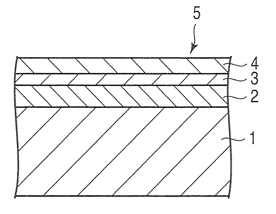
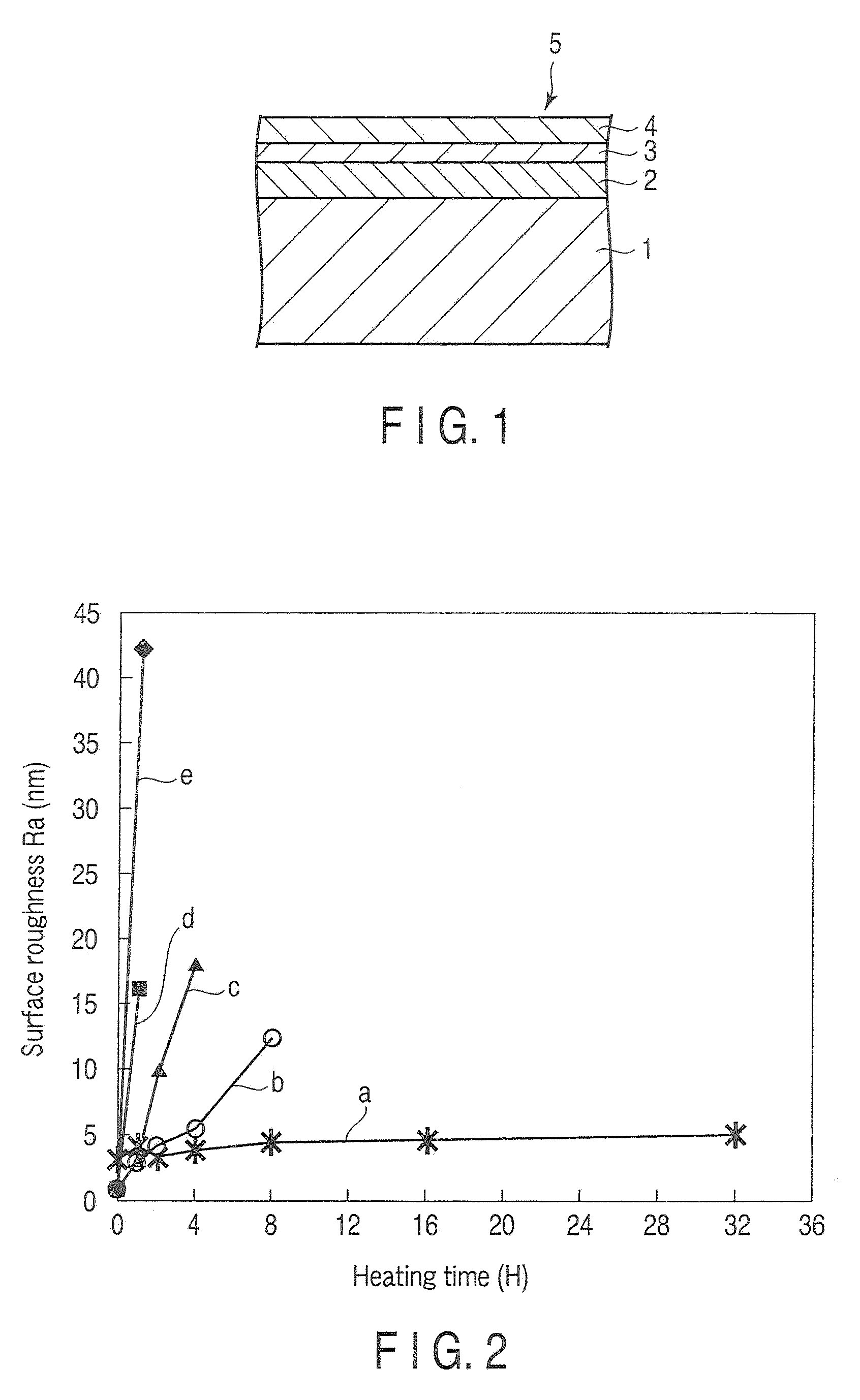
[0026]FIG. 1 is a partial cross section showing a glass-shaping mold according to Example 1 of the present invention. In FIG. 1, reference numeral 1 denotes a steel base member. A crystallized, machined layer 2, an intermediate layer 3 and a mold-releasing layer 4 are formed on the base member 1 sequentially. The machined layer 2 is a layer of a nickel alloy containing 12 wt % of P (phosphorus). The intermediate layer 3 is a layer made of chromium (Cr). The mold-releasing layer 4 is a layer of an alloy containing iridium (Ir) and rhenium (Re).
[0027]The glass-shaping mold 5 shown in FIG. 1 is manufactured as follows: First, a nonelectrolyte Ni—P coating having a thickness of 100 μm was formed on the steel base member 1 and was then subject to heat treatment at 530° C. for two hours. The Ni—P coating was crystallized, thereby forming the machined layer 2. After the machined layer 2 was worked by means of a turning diamond tool, an intermediate layer 3 made of Cr and having a thickness...
example 2
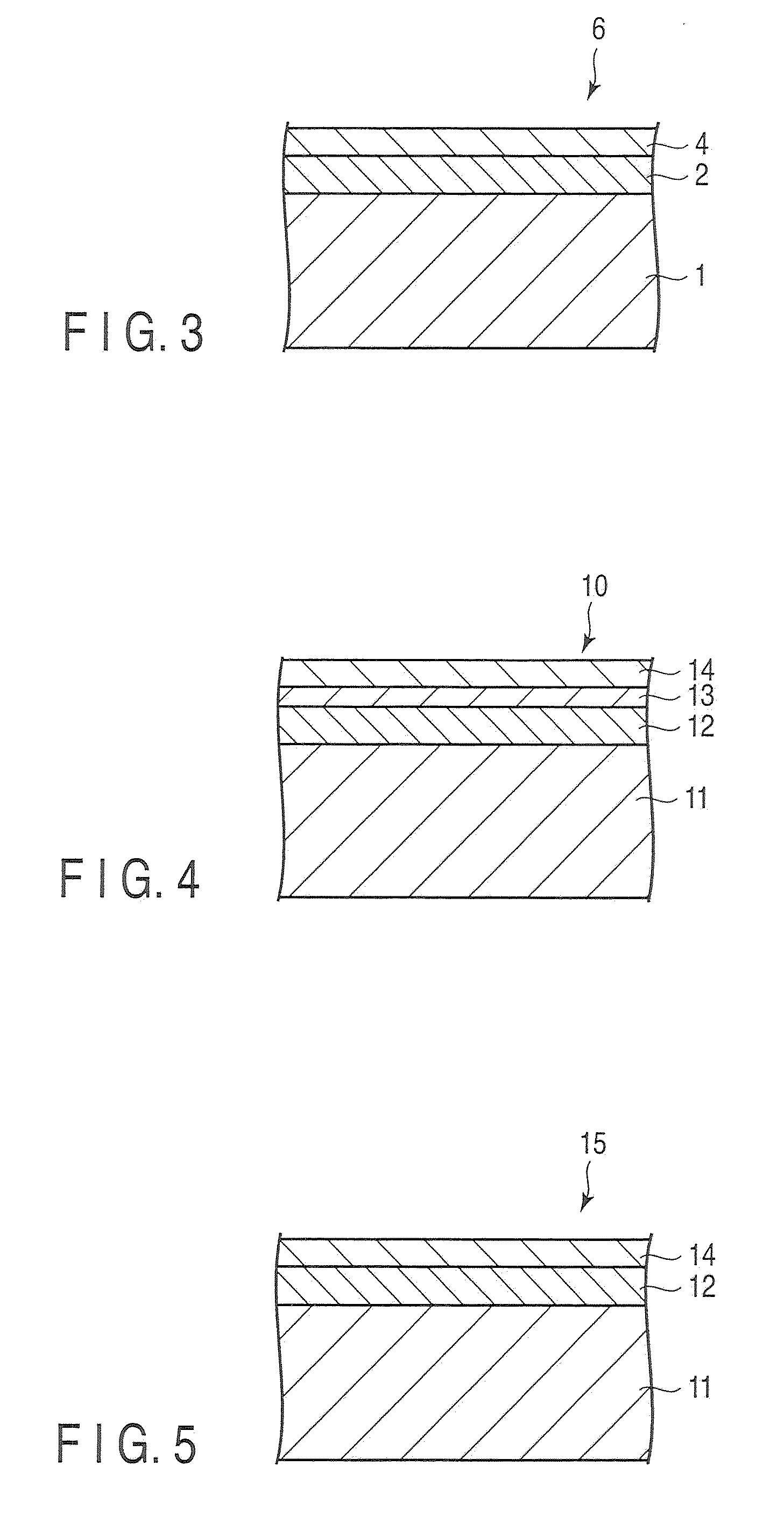
[0031]FIG. 3 is a partial cross section showing a glass-shaping mold according to Example 2 of the present invention. The corresponding members to those in FIG. 1 are denoted by the same reference numerals, and a detailed description of them will be omitted. The glass-shaping mold 6 has a structure wherein a steel base member 1 is overlaid with a crystallized, machined layer 2 and a mold releasing layer 4 which are sequentially formed.
[0032]The glass-shaping mold 6 shown in FIG. 3 is manufactured as follows: First, a nonelectrolyte Ni—P coating having a thickness of 100 μm was formed on the steel base member 1 and was then subject to heat treatment at 530° C. for two hours. The Ni—P coating was crystallized, thereby forming the machined layer 2. After the machined layer 2 was worked by means of a turning diamond tool, a mold-releasing layer 4 made of Ir-25% Re by weight and having a thickness of 300 nm was formed by sputtering. In this manner, the glass-shaping mold 6 was manufactur...
example 3
[0034]FIG. 4 is a partial cross section showing a glass-shaping mold according to Example 3 of the present invention. Reference numeral 11 in FIG. 4 denotes a steel base member. A crystallized, machined layer 12, an intermediate layer 13 and a mold-releasing layer 14 are sequentially formed on the base member 11. The machined layer 12 is a layer of nickel alloy containing 10% by weight of P (phosphorus), i.e., a (Ni-10 wt % P) layer. The intermediate layer 13 is a layer made of nickel (Ni). The releasing layer 14 is a layer of an alloy containing iridium (Ir), rhenium (Re) and 3 at %-carbon (C).
[0035]The glass-shaping mold 10 shown in FIG. 4 is manufactured as follows: First, a nonelectrolyte Ni—P coating having a thickness of 100 μm was formed on the steel base member 1 and was then subject to heat treatment at 530° C. for two hours. The Ni—P coating was crystallized, thereby forming the machined layer 12. After the machined layer 12 was worked by means of a turning diamond tool, a...
PUM
| Property | Measurement | Unit |
|---|---|---|
| thickness | aaaaa | aaaaa |
| thickness | aaaaa | aaaaa |
| thickness | aaaaa | aaaaa |
Abstract
Description
Claims
Application Information