
Method and apparatus for coil array compression

a coil array and compression method technology, applied in the field of magnetic resonance methods, can solve the problems of inability to accurately determine the sensitivity and noise characteristics of the material, and achieve the effect of greater adaptability of the linear combination step and higher accuracy

Inactive Publication Date: 2010-01-21
EIDGENOSSISCHE TECHN HOCHSCHULE ETH +1
View PDF5 Cites 15 Cited by
  • Summary
  • Abstract
  • Description
  • Claims
  • Application Information

AI Technical Summary

Benefits of technology

[0010]c) reconstructing an image from said plurality of transformed signals;wherein said transformation matrix A is determined so as to substantially maximize the signal-to-noise ratio in a preselected region of said reconstructed image for given sensitivity characteristics and noise statistics of said plurality of receiver coils.
[0019]As it is well-known, an analog-to-digital conversion step is generally applied to the signals obtained from magnetic resonance imaging receiver coils, which is achieved by means of so-called “Receiver and A / D-Converter” devices. In the context of the present invention, such analog-to-digital conversion may be applied either to said original signals prior to linear combination thereof (claim 11) or to said transformed signals (claim 12). According to the first variant, the linear combination step is carried out with a digitized version of the original signals; this will generally provide a higher accuracy and a greater adaptability of the linear combination step, but it requires a receiver and A / D-converter device for each one of said n receiver coils (claim 14). According to the second variant, the linear combination step is carried out with the non-digitized original steps; this will require installation of suitable analog circuitry for linear combination, but it allows to reduce the number of receiver and A / D-converter devices from n to m (claim 15).

Problems solved by technology

Moreover, it shall be understood that practical determination of sensitivity and noise characteristics inevitably has certain limits in its accuracy.

Method used


Image

  • Method and apparatus for coil array compression
  • Method and apparatus for coil array compression
  • Method and apparatus for coil array compression

Examples


Embodiment Construction

[0032]The exemplifications set out herein are not to be construed as limiting the scope of this disclosure or the scope of this invention in any manner.

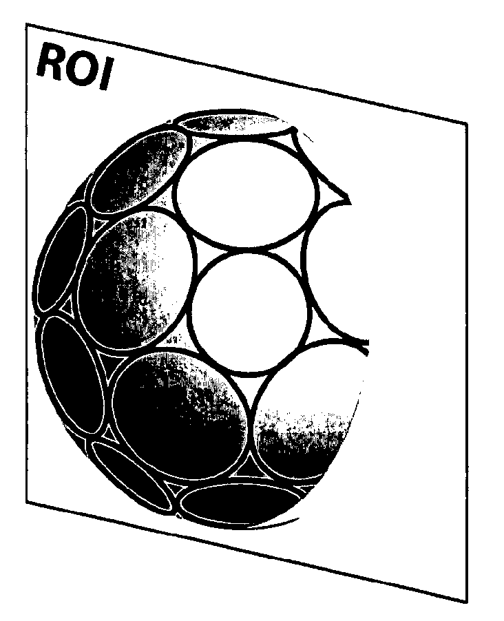
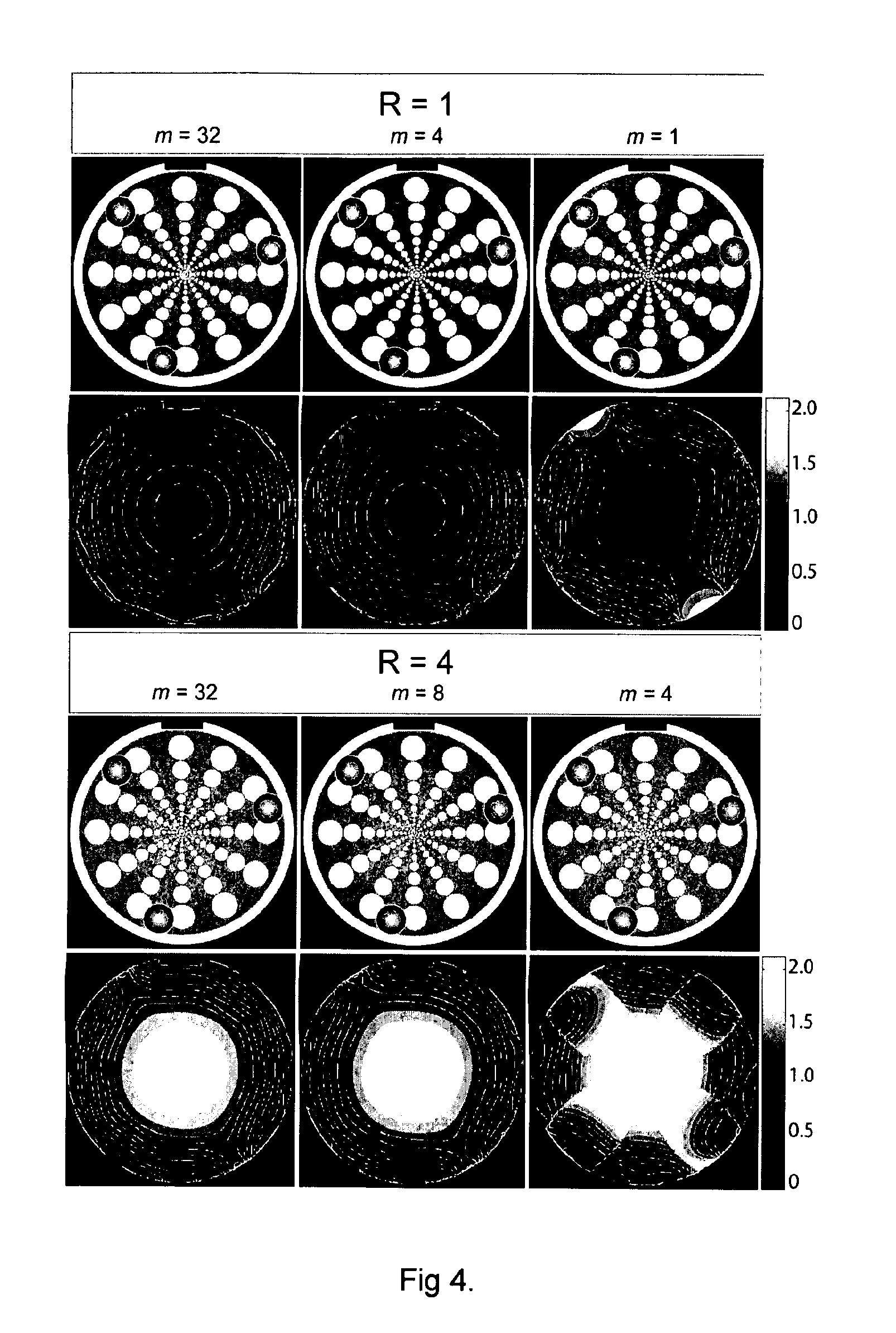
[0033]The subject invention relates to a method and apparatus for combining signals from multiple coil elements which are operated in parallel based on knowledge of the sensitivities of the individual coil elements with respect to a volume-of-interest which is preferably smaller than the imaging volume selected by the MR experiment.

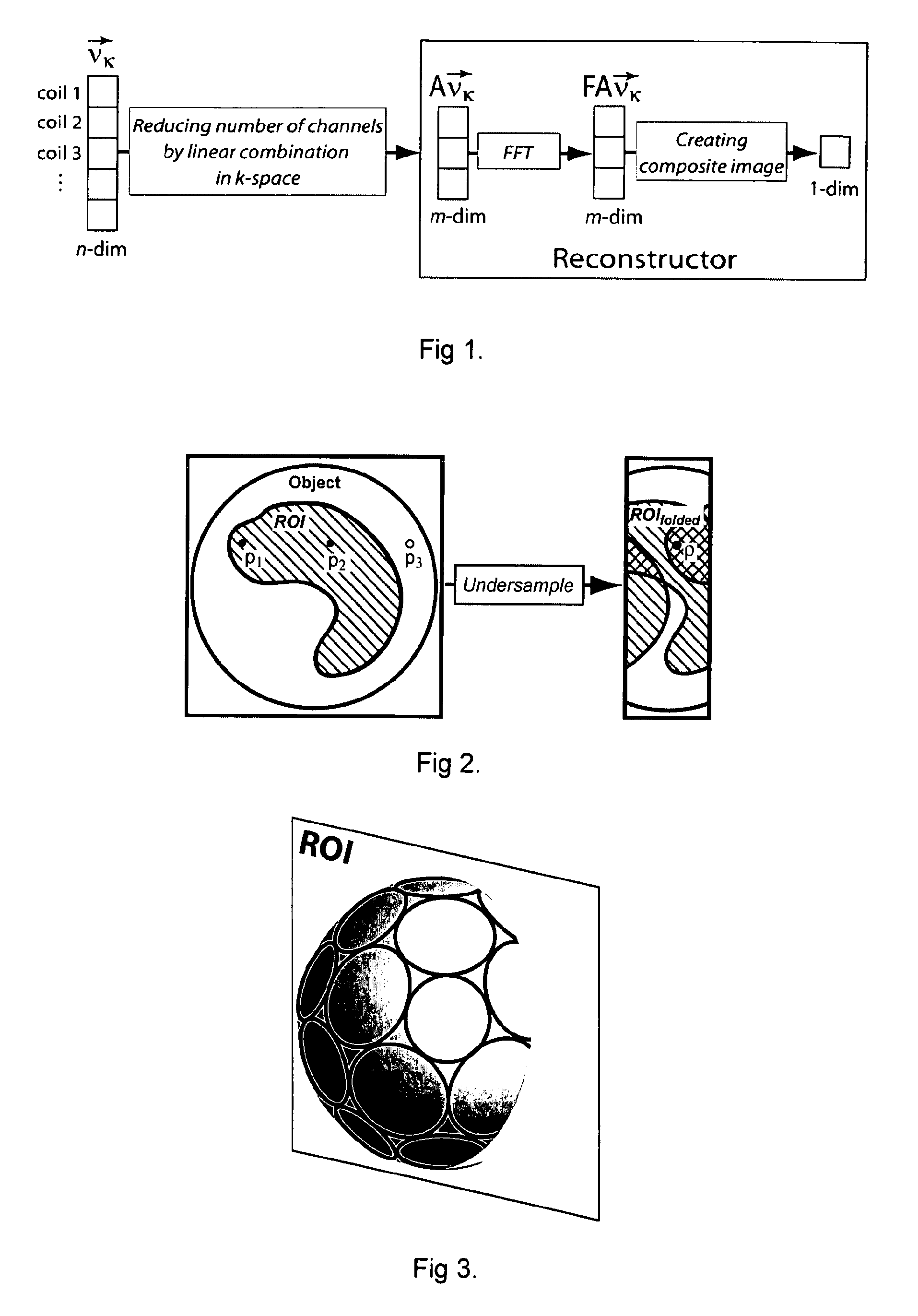
[0034]In detail, the sampled signals from n physical coils (stored in vector νK) are combined in the time-domain using linear combination A creating a reduced set of m virtual coils contained in vector ν′K under the constraint that the signal-to-noise ratio in the reconstructed image within the volume-of-interest is maximized:

i′ê=Aiê  [1]

The MR signals from the m virtual coils are passed on to the reconstructor unit for image reconstruction purposes (FIG. 1). The Fourier transformation F and the subsequent...


PUM


Abstract

A method of processing magnetic resonance imaging signals from a plurality of receiver coils of a magnetic resonance imaging system, comprises the steps of receiving from said plurality of receiver coils a corresponding plurality of original signals in the time-domain forming an n-dimensional signal vector νk wherein n is the number of receiver coils; linearly combining said original signals so as to obtain a plurality of transformed signals forming an m-dimensional transformed signal vector ν′k wherein m is smaller than n and wherein said step of linearly combining is represented by a linear transformation matrix A; and reconstructing an image from said plurality of transformed signals. Said transformation matrix A is determined for given sensitivity characteristics and noise statistics of said plurality of receiver coils so as to substantially maximize the signal-to-noise ratio in a preselected image region or volume which is preferably smaller than the imaging slice or volume selected by the magnetic resonance experiment.

Description

BACKGROUND OF THE INVENTION [0001]The invention relates to magnetic resonance (MR) methods employing multiple receive antennae which are operated in parallel. Such methods are known as phased-array or coil array imaging techniques. With suitable combination of the signals from multiple physical coils, the signal-to-noise ratio (SNR) in the images is improved relative to methods using a single receive coil (U.S. Pat. No. 4,871,969). Further methods which make use of the spatial encoding capabilities of coil arrays to reduce the number of magnetic field gradient-based spatial encoding steps are known as parallel imaging methods (e.g. U.S. Pat. No. 6,326,786 B1). These methods allow speeding up the MR signal collection process for forming images by deliberately undersampling the data space in the Fourier domain of the image.[0002]In aforementioned methods, MR signals are detected by each of the individual antennae in a coil array and processed in parallel by the receiver unit which typ...

Claims


Application Information

Patent Timeline
IPC IPC(8): G01R33/48G01R33/44
CPCG01R33/3415
Inventor BUEHRER, MARTINPRUESSMANN, KLAASKOZERKE, SEBASTIAN
Owner EIDGENOSSISCHE TECHN HOCHSCHULE ETH
Learn More