
System And Method To Determine The Impedance Of A Disconnected Electrical Facility

a technology of electrical facilities and impedance, applied in the field of systems, can solve problems such as fatal situations for workers, damage to surrounding equipment, and forgetting safety ground consequences

Active Publication Date: 2010-01-21
HITACHI ENERGY SWITZERLAND AG
View PDF7 Cites 22 Cited by
  • Summary
  • Abstract
  • Description
  • Claims
  • Application Information

AI Technical Summary

Benefits of technology

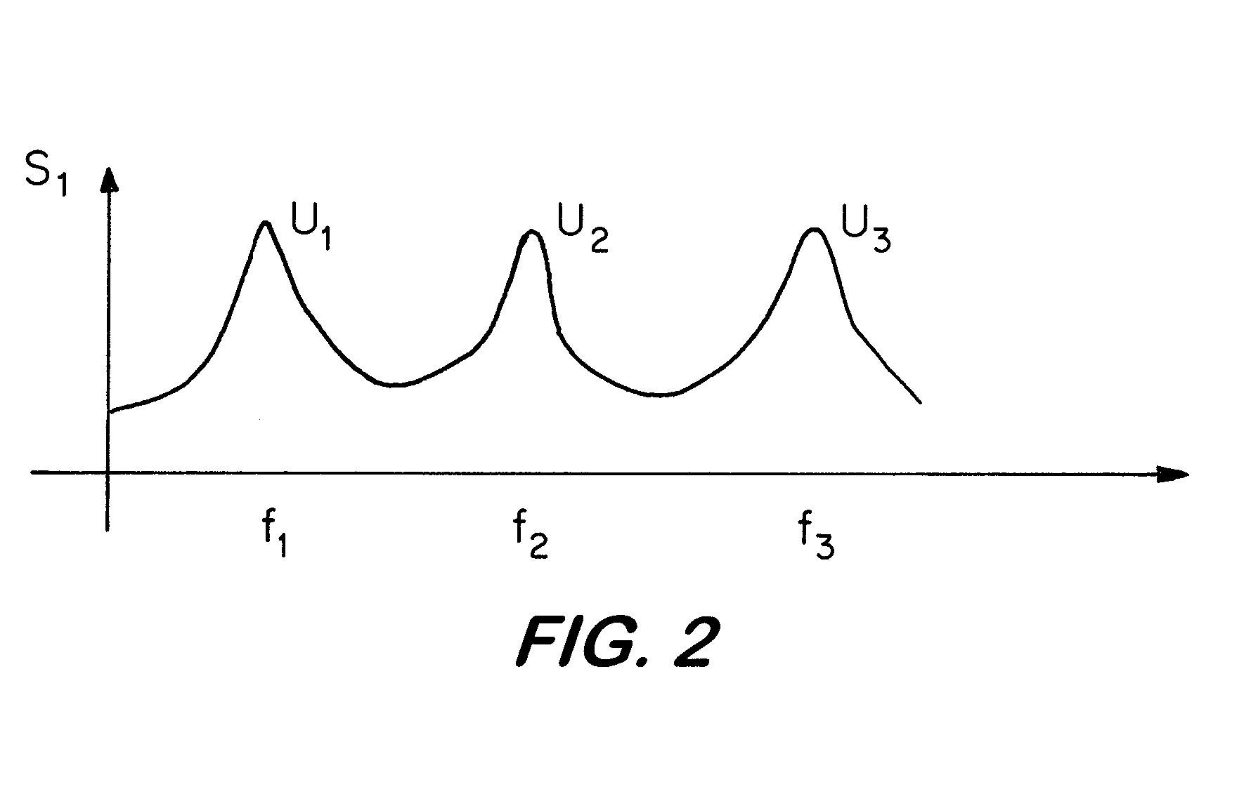
[0025]In the European patent application 06445061.2, the method of dielectric spectroscopy is used to improve the accuracy of a ground fault detection method applied to a stator winding of a multiple-phase generator. A ground fault in the stator winding, which is an internal fault and which can be caused by physical damage or ageing of the insulation material of the winding, precedes generally all other possible faults of the generator, such as phase-to-phase faults of the stator. Accordingly, it is useful to detect the ground fault in the winding to prevent more severe faults in the generator. The stator of the generator is wye connected and the neutral point is connected to ground. For the dielectric spectroscopy, an AC test signal is injected between the neutral point and ground and the response of the stator to that AC signal is measured. From the measurements, a fault impedance to ground is determined, where the fault impedance is modelled as a fault resistance in parallel to a capacitance to ground.
[0045]In case the safety state indicates a permanent short circuit fault for an electrical facility being disconnected during operation, it is furthermore possible to determine the location of the fault. This allows counter-measures for removal of the fault to be applied faster.

Problems solved by technology

An electrical facility is an installation or device, the operating current of which is high enough to become dangerous for an operator or to cause some damage in the surrounding equipment in case of an unwanted earthing.
To forget the safety ground can have serious consequences in mainly two different situations.
First, in case that the safety ground is not properly installed on the facility and that a worker approaches.
Even though the facility is no longer energized itself, it may have picked up induced voltages from energized equipment in its neighbourhood.
In the worst case, this situation can be fatal for the worker.
If the safety ground connector was forgotten to be removed after finishing the maintenance, an unwanted earthing of the facility occurs.
This may cause severe destructions.
One such reason is if it is subject to a self clearing fault during operation, like for instance being subject to a short-circuit fault caused by the electrical facility being struck by lightning.
A forgotten safety ground or such a short-circuit fault has especially severe consequences in case of a three-phase electrical facility, such as a transformer or a capacitor bank in a substation of a power network or a three-phase power transmission or distribution line.
A three-phase fault generally has a very severe impact on the electrical facility and its surrounding equipment.
Three-phase faults spread over a large area of the related power network as a sudden depression of voltage or voltage sag, which might trip sensitive devices.
The efforts needed to reinstate the devices and the power network, are of serious concern.
The coordination of maintenance work is difficult, particularly when several crews from different contractors work simultaneously in different points of a line or substation.
And statistics show that in most accidents on power facilities leading to personal injuries or three-phase faults of a line or substation, human errors are involved.
The central unit makes it then impossible to connect a high voltage to ground to the high voltage conductor.
The hardware needed for this warning system is considerable; in particular the additional conductor makes the installation costly.

Method used


Image

  • System And Method To Determine The Impedance Of A Disconnected Electrical Facility
  • System And Method To Determine The Impedance Of A Disconnected Electrical Facility
  • System And Method To Determine The Impedance Of A Disconnected Electrical Facility

Examples


Embodiment Construction

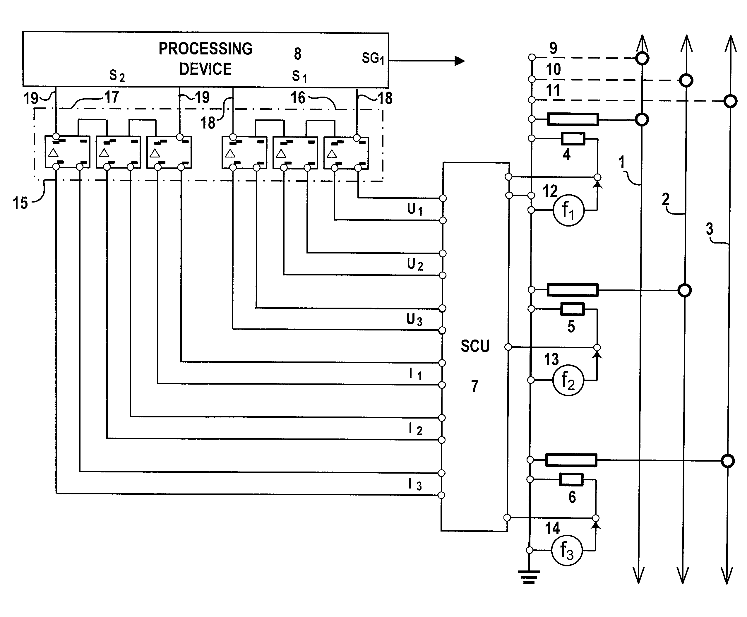
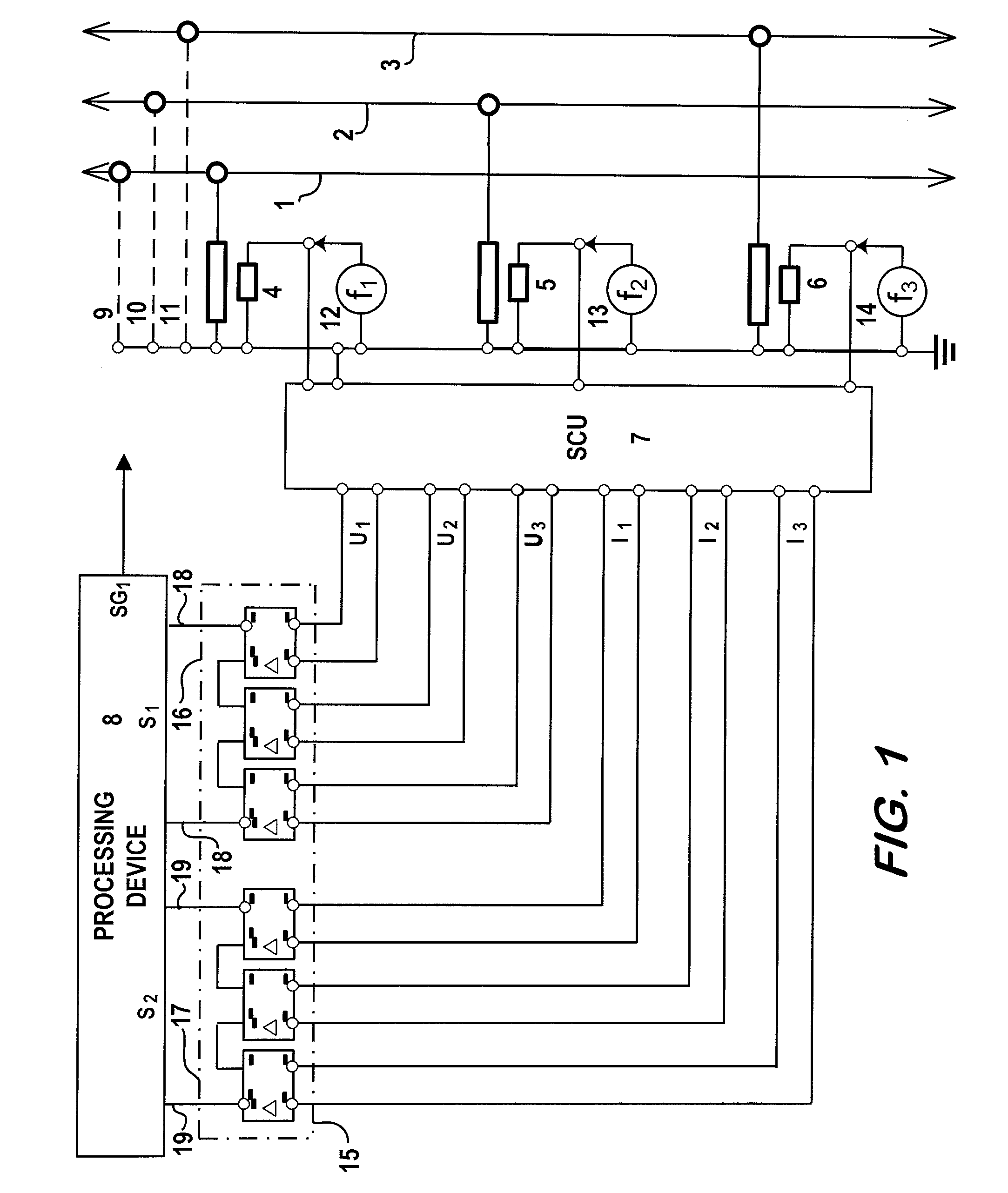
[0051]FIG. 1 shows a three-phase power line with the three phases 1, 2 and 3, where the power line can be a power transmission or a power distribution line. Each of the three phases 1, 2 and 3 is connected to a voltage transformer 4, 5 and 6, which is used to transform the voltages in the phase down to a measurable level. The voltage transformers 4, 5 and 6 are all connected to ground. The arrangement of voltage transformers 4, 5 and 6 is regarded in the following as an electric circuit being connected with the three-phase line, where the three-phase line is regarded as electrical facility.

[0052]A system consisting of a signal injection unit, a signal conversion unit 7 and a processing device 8 is used to measure the neutral to ground impedances of the phases 1, 2 and 3 in order to detect if a safety ground 9, 10 and 11 is present for each of the phases 1, 2 and 3. The signal injection comprises three signal generation units 12, 13 and 14, where the first signal generation unit 12 g...


PUM


Abstract

A signal injection unit injects a test signal at a main frequency between a reference point of an electric circuit and ground, where the electric circuit is connected with the facility and injects another test signal at a second main frequency between a reference point of the electric circuit and ground. A signal conversion unit measures first and second response voltages and first and second response currents in the electric circuit, where the response voltages and the response currents result from the test signals. A processing device determines impedances to ground of the facility from the response voltages and the response currents, analyses impedances to ground of the facility, where this analysing includes comparing each determined impedance to ground with a predetermined value, and determines a safety state of the disconnected electrical facility based on the analysed impedances to ground.

Description

CROSS-REFERENCE TO RELATED APPLICATIONS[0001]The present application is a continuation of pending International patent application PCT / EP2007 / 064458 filed on Dec. 21, 2007 which designates the United States and claims priority from European patent application EP06126985.8 filed on Dec. 22, 2006, the content of which is incorporated herein by reference.FIELD OF THE INVENTION[0002]The invention relates to a system and a method to determine the impedance of an electrical facility being disconnected from its high or medium voltage power supply.BACKGROUND OF THE INVENTION[0003]An electrical facility is an installation or device, the operating current of which is high enough to become dangerous for an operator or to cause some damage in the surrounding equipment in case of an unwanted earthing. This is usually true for all high and medium voltage facilities used in power generation, transmission and distribution. Whenever maintenance or repair work is to be done on the electrical facility...

Claims


Application Information

Patent Timeline
Patent Type & Authority Applications(United States)
IPC IPC(8): G01R27/28G08B21/00
CPCG01R27/16H02H11/001H02H5/105
Inventor OLGUIN, GABRIEL
Owner HITACHI ENERGY SWITZERLAND AG
Learn More