Display device

a technology of a display device and a display panel, which is applied in the direction of identification means, instruments, substation equipment, etc., can solve the problems of long-term studies conducted, frequent cracks in the glass, and inability to prevent cracks, so as to reduce the thickness, and increase the strength of the liquid crystal panel

Active Publication Date: 2010-01-21
DAWNCREST IP LLC
View PDF17 Cites 26 Cited by
  • Summary
  • Abstract
  • Description
  • Claims
  • Application Information

AI Technical Summary

Benefits of technology

[0006]On the other hand, the strength of the liquid crystal panel is increased with an aid of tempered glass which is bonded to a display surface of the liquid crystal panel. The tempered glass may increase the strength thereof particularly against an impact of a falling ball or the like, whereas there arises a problem that, when being applied with a weight of a pressure, the liquid crystal panel is broken before the tempered glass is broken.
[0007]Here, the above-mentioned problem is solved by the following manner. In a structure in which a transparent plate is entirely bonded via an optical adhesive layer to at least one of a front surface and a back surface of a liquid crystal panel in which liquid crystals are held between two transparent substrates, an amount of warp by which the liquid crystal panel alone is broken due to a pressure is set equal to or larger than an amount of warp by which the transparent plate alone is broken due to the pressure. More specifically, the transparent substrates of the liquid crystal panel are further reduced in thickness. With this structure, when being applied with a load, the transparent plate is broken before or simultaneously with breakage of the liquid crystal panel. Another transparent plate may be further entirely bonded to the transparent plate via an optical adhesive layer in order to further increase the load resistance.
[0008]According to the liquid crystal display device with the above-mentioned structure, it is possible to provide a liquid crystal display device in which the glass of the liquid crystal panel may be reduced in thickness and which is high in strength. Further, as the transparent plate, thin tempered glass is bonded to the liquid crystal panel via the optical adhesive layer by lamination, which enables to increase the load resistance. The structure described above is applicable not only to the liquid crystal panel but also to other display panels.

Problems solved by technology

In a liquid crystal panel manufactured with thin glass, cracks frequently occur in the glass due to a drop impact or a weight of a pressure.
However, it has been unsuccessful to prevent the cracks due to an impact from occurring in the liquid crystal panel, particularly in the lower glass.
In addition, studies have been conducted for a long time to change the glass substrate of a liquid crystal panel to a substrate made of plastic or a polymer film.
However, reliability in a gas barrier to be formed on the plastic substrate or the film substrate has not been secured, and therefore, a liquid crystal panel having a plastic substrate or a film substrate as described above has not yet to be sold commonly in large volume.
The tempered glass may increase the strength thereof particularly against an impact of a falling ball or the like, whereas there arises a problem that, when being applied with a weight of a pressure, the liquid crystal panel is broken before the tempered glass is broken.

Method used


Image

  • Display device
  • Display device

Examples


first embodiment

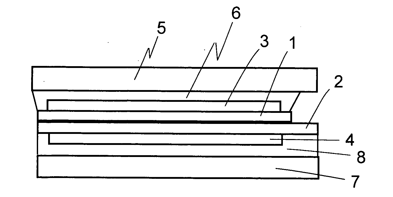
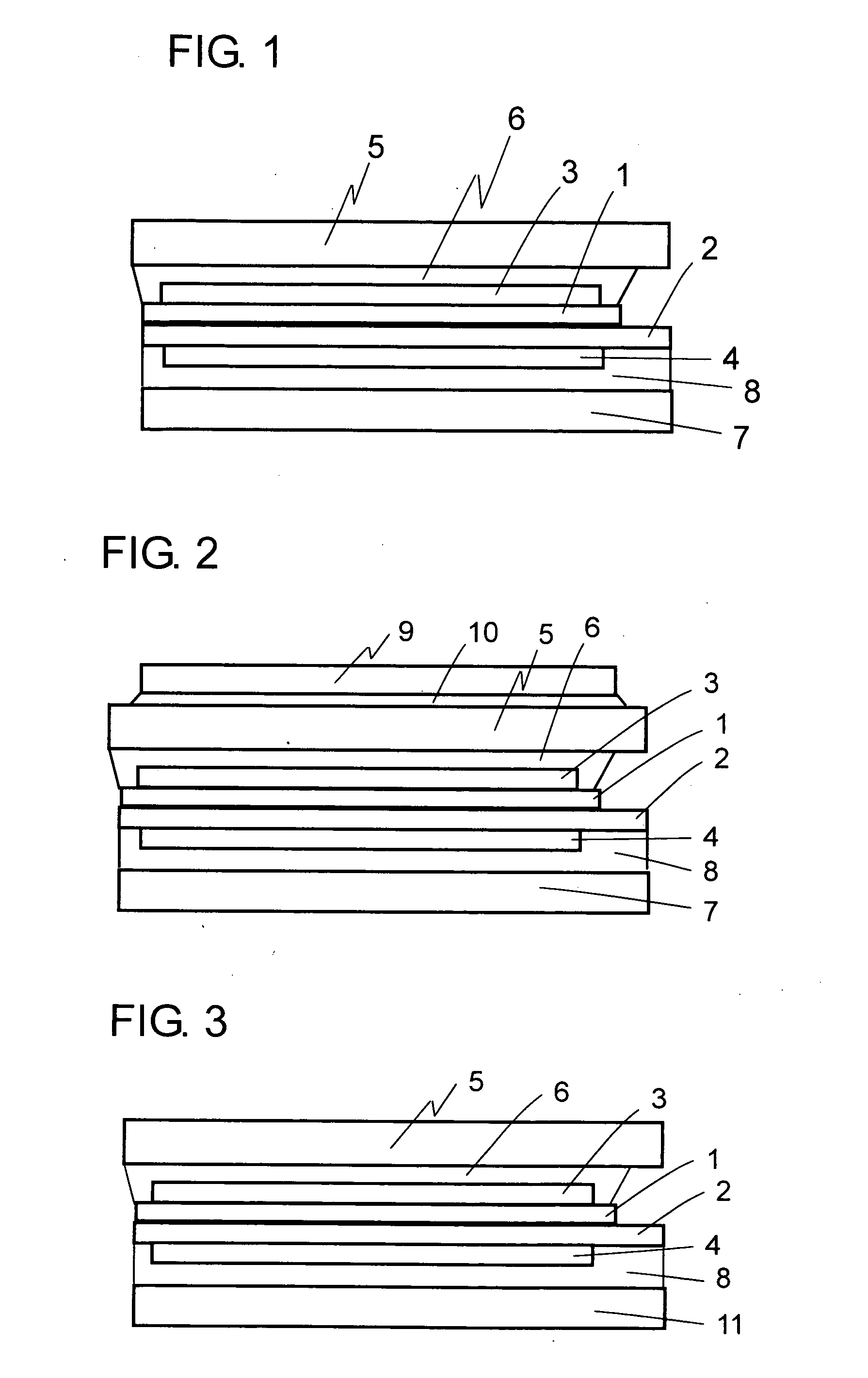
[0029]FIG. 1 schematically illustrates a cross-sectional structure according to a first embodiment. A liquid crystal panel has a structure in which a liquid crystal layer is held in a gap between a transparent substrate 1 provided on a display surface side and an opposing transparent substrate 2 provided on a back surface side. On the transparent substrate 1, a color filter and a transparent electrode are formed. On the opposing transparent substrate 2, a TFT array is formed. A drive signal is output from a driver IC (not shown) to drive the liquid crystals. Light for which its vibration direction is selected at an upper polarizing plate 3 bonded to the transparent substrate 1 on the display surface side and a lower polarizing plate 4 bonded to the opposing transparent substrate 2 on the back surface side is incident from a back light (not shown). The vibration direction of the light is changed in the liquid crystal layer. Display is performed based on whether the upper polarizing p...

second embodiment

[0033]FIG. 2 schematically illustrates a cross-sectional structure of a display device according to a second embodiment. The second embodiment employs a structure in which sapphire 9 having a thickness of 0.3 mm is further bonded using an optical adhesive 10 to the tempered glass 5 provided on the display surface side of the display device according to the first embodiment. A refractive index of sapphire is 1.76, which is larger compared with 1.54 of glass. For this reason, in view of transmittance, it is preferable that an AR film formed by sputtering a material having a lowered refractive index be formed on a surface of the sapphire, or alternatively that a refractive index of the optical adhesive 10 be set to an intermediate level between those of sapphire and glass.

[0034]Sapphire has a higher Young's modulus than that of soda-lime glass, and therefore is resistant to cracks even when being thinned. According to a falling ball test, the same strength characteristics are obtained ...

third embodiment

[0037]FIG. 3 schematically illustrates a cross-sectional structure of a display device according to a third embodiment. The third embodiment employs a structure in which tempered glass 11 having a satin finished surface is used on the back surface side of the display device according to the first embodiment. In a structure in which a back light is provided behind a liquid crystal panel to illuminate the liquid crystal panel, the back light includes a light guide plate and a light source, and light from the LED light source is introduced from a side surface of the light guide plate to achieve surface emission by means of a reflection pattern formed on a front surface of the light guide plate. In this case, in order to increase luminance, two prism sheets each having lenses continuously formed thereon in one direction are arranged on an emission surface so that the directions of the lenses are orthogonal to each other, and conventionally, a diffusion plate is further arranged thereon....


PUM

PropertyMeasurementUnit
thicknessaaaaaaaaaa
thicknessaaaaaaaaaa
thicknessaaaaaaaaaa

Abstract

To prevent a reduction in load resistance of a liquid crystal panel which is caused along with a reduction in thickness thereof, tempered glass is entirely bonded to both of front and back surfaces or one of the surfaces of the liquid crystal panel using an optical adhesive, and an amount of warp by which the liquid crystal panel alone is broken due to a pressure is set equal to or larger than that in a case of the tempered glass.

Description

TECHNICAL FIELD[0001]The present invention relates to a display device which is used in a portable device including a cellular phone, a PDA, or an electronic dictionary. In particular, the present invention relates to a technology of increasing strength of a liquid crystal panel manufactured with a thin glass substrate.BACKGROUND ART[0002]Due to growing demand for a reduction in thickness of a portable device such as a cellular phone, a reduction in thickness of glass of a liquid crystal panel has been attained up to 0.35 mm to 0.25 mm. In the cellular phone, a transparent plate such as a transparent touch panel or a transparent cover plate is bonded to a liquid crystal panel in some cases. There is known a method of entirely bonding a touch panel to a display panel using an optical adhesive (see JP 09-274536 A, for example).[0003]In the structure described above, drop impact resistance of the liquid crystal panel is naturally increased to some extent. For the transparent cover plat...

Claims


Application Information

Patent Timeline
Patent Type & Authority Applications(United States)
IPC IPC(8): G02F1/1333
CPCG02F1/1333G02F2001/133302H04M1/0266G02F2201/54G02F2202/28G02F2201/503G02F1/133302G02F1/1335G09F9/00
Inventor MATSUHIRA, TSUTOMU
Owner DAWNCREST IP LLC
Why Eureka
Try Eureka