Light diffusion plate, composition liquid for forming a light diffusion layer and process for producing light diffusion plate

a technology of composition liquid and diffusion plate, which is applied in the direction of lighting and heating apparatus, instruments, optical elements, etc., can solve the problems of increased cost, uneven brightness in display screens, and difficult above diffusion plates having resin substrates, and achieve high transmittance and sufficient diffusion properties, and the light emission quality of backlight units is not deteriorated. , the effect of high rigidity

Inactive Publication Date: 2010-01-21
ASAHI GLASS CO LTD
View PDF0 Cites 5 Cited by
  • Summary
  • Abstract
  • Description
  • Claims
  • Application Information

AI Technical Summary

Benefits of technology

[0031]In the light diffusion layer of the present invention, since the absolute value Δn of the refractive index difference between the matrix and the light diffusion agent constituting the light diffusion layer is 0.05 or more and less than 0.5 and the volume ratio of the light diffusion agent in the light diffusion layer is 30% or more, it is possible to achieve both high transmittance and sufficient diffusion property.
[0032]Further, since the substrate is made of a glass, unlike a diffusion plate made of a resin, there occurs no warp, yellowing or thermal deformation due to heat of e.g. light sources, and there occurs no warp due to absorption of moisture. Accordingly, even when the light sources and the diffusion plate are disposed closely to each other, the light emission quality of a backlight unit is not deteriorated. Further, since the light diffusion plate has a high rigidity, it does not warp even when it has a large size. Accordingly, the light diffusion plate of the present invention is suitable for size-increase or thickness-reduction of backlight units.
[0033]Further, the coating liquid of the present invention can exhibit desired diffusion properties even when the light diffusion layer has a small thickness of from 5 to 100 μm. Further, since the light diffusion layer can exhibit the diffusion properties even when the light diffusion layer has a small thickness of from 5 to 100 μm, it can be produced by a single coating operation with the coating liquid, and the coating liquid has an excellent economical efficiency.

Problems solved by technology

However, it is difficult for the above diffusion plate having a resin substrate to achieve high brightness with a large size or a small thickness for the following reasons.
First of all, a large sized diffusion plate tends to warp or deflect, which causes uneven brightness in a display screen.
To solve this problem, it is necessary to increase the thickness of the substrate, which prevents the reduction of the thickness of a backlight unit and increases the cost.
This tends to cause thermal deformation or yellowing of the diffusion plate, or warp of the diffusion plate due to emission of moisture absorbed in the diffusion plate.
Further, since its transmittance is only from 10 to 40%, the brightness of a backlight unit employing the diffusion plate will be insufficient.
In a step of pasting the film, when the film has a large area, it is difficult to prevent mixing of bubbles or foreign matter, which increases the cost.
Further, with respect to the diffusion plate comprising a glass having a surface with irregularities, light diffusion occurs only at the glass surface and its diffusion performance is inherently limited.
Further, it is difficult to produce fine irregularities by sandblast, and fine unevenness of brightness may occur on a screen.
However, according to Examples 1 and 2 of the document, the diffusion layer is formed by carrying out coating twice, which may require a long production time and cause a problem of the cost.

Method used


Image

  • Light diffusion plate, composition liquid for forming a light diffusion layer and process for producing light diffusion plate
  • Light diffusion plate, composition liquid for forming a light diffusion layer and process for producing light diffusion plate
  • Light diffusion plate, composition liquid for forming a light diffusion layer and process for producing light diffusion plate

Examples


example 1

Preparation of Coating Liquid A

[0087]50 g of a polyester resin (Vyron 220 manufactured by Toyobo Co., Ltd.; specific gravity: 1.26; average molecular weight: 5,000) and 50 g of a diluted solvent (G-004 solvent, manufactured by Teikoku Printing Inks Mfg. Co., Ltd.) were mixed and stirred to prepare as a matrix-forming component a polyester resin solution “a” containing a solid state content of 50 mass %.

[0088]100 g of the polyester resin solution “a”, 8.1 g of an isocyanate type curing agent (210 curing agent manufactured by Teikoku Printing Inks Mfg. Co., Ltd.) as a curing agent, 1.1 g of an epoxy type silane coupling agent (KBM-403 manufactured by Shin-Etsu Chemical Co., Ltd.), 1 g of a defoaming agent (manufactured by Teikoku Printing Inks Mfg. Co., Ltd.), 0.11 g of dibutyltin dilaurate (DBTDL) as a curing agent, and 66.7 g of benzoguanamine-formaldehyde-condensed resin fine particles (Epostar M05, manufactured by Nippon Shokubai Co., Ltd.; specific gravity: 1.4; average particle ...

example 2

[0090]A light diffusion plate B was obtained in the same manner as Example 1 except that the light diffusion agent of Example 1 was changed to 133.3 g of alumina fine particles [CB-A05S manufactured by Showa Denko K.K.; specific gravity: 3.98; average particle size: 3 μm; refractive index: 1.76]. The thickness of the light diffusion layer of the light diffusion plate B was 17 μm.


PUM


Abstract

A conventional light diffusion plate provided in a direct type backlight unit to be employed for e.g. a liquid crystal display, has problems in that it does not have a sufficient diffusion performance, it is difficult to increase the size, and it is difficult to produce such a light diffusion plate at low cost.
A light diffusion plate comprising a glass substrate and a light diffusion layer formed on the glass substrate, wherein the light diffusion layer comprises a matrix and a light diffusion agent, the absolute value Δn of the refractive index difference between the matrix and the light diffusion agent is 0.05 or more and less than 0.5, and the volume ratio of the light diffusion agent in the light diffusion layer is 30% or more.

Description

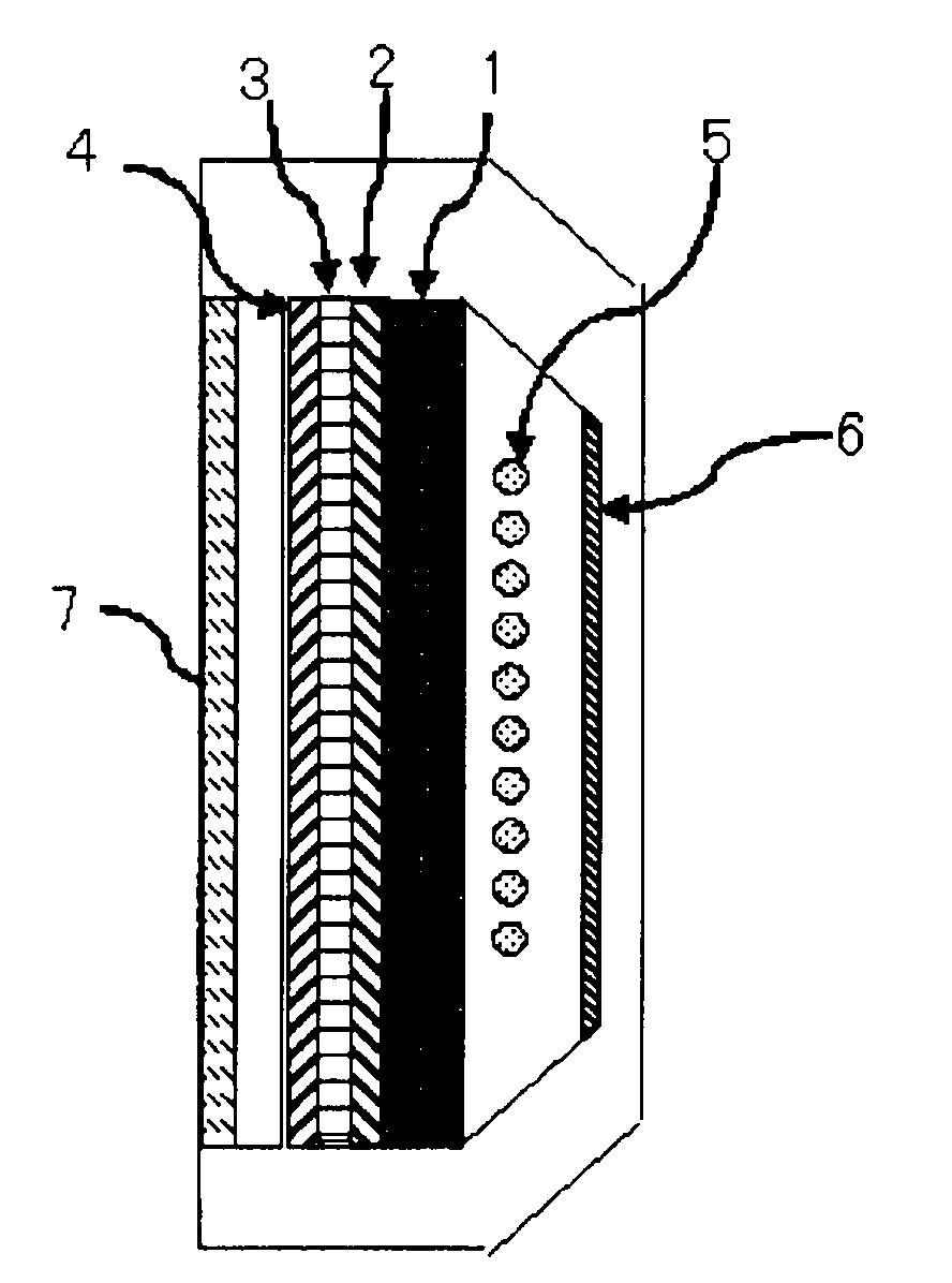
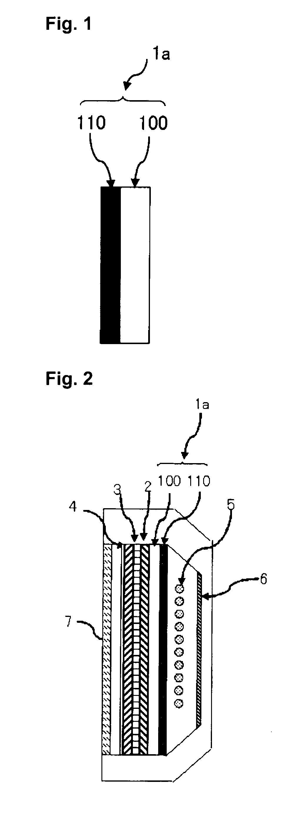
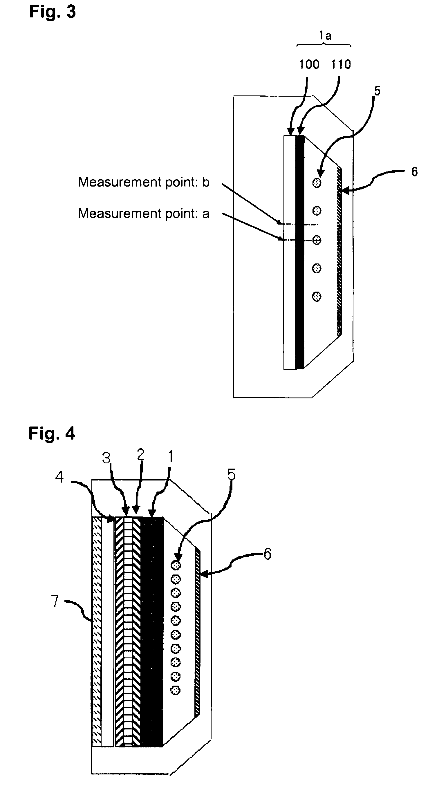
TECHNICAL FIELD[0001]The present invention relates to a light diffusion plate for a direct type backlight unit to be employed for e.g. a liquid crystal display, and to a coating liquid for forming a light diffusion layer that is employed for production of such a light diffusion plate.BACKGROUND ART[0002]Liquid crystal displays are employed for monitors of personal computers, home-use TVs, cell phones, etc. In recent years, along with an increase in demand for such liquid crystal displays for home-use TVs, a rapid increase in the display size is in progress. Backlight units for providing light to liquid crystal TVs are of a side light type and a direct type. For the application to home-use TVs requiring a large display size and a high brightness, backlight units of a direct type are mainly employed.[0003]A direct type backlight unit usually has, as shown in FIG. 4, a light source 5; a light diffusion plate 1 disposed on a front side of the light source for erasing a light source imag...

Claims


Application Information

Patent Timeline
Patent Type & Authority Applications(United States)
IPC IPC(8): F21V7/04C08L67/00B05D5/06
CPCG02B5/0242G02B5/0268G02F2201/086G02F1/133606G02B5/0278G02B5/02G02F1/1335
Inventor INOKUMA, HISAOTAKAKI, SATORU
Owner ASAHI GLASS CO LTD
Why Eureka
Try Eureka