
Semiconductor device manufacturing method, semiconductor device manufacturing apparatus, computer program and storage medium

a semiconductor and manufacturing method technology, applied in the direction of semiconductor/solid-state device details, chemical vapor deposition coating, coating, etc., can solve the problems of reduced production yield, copper line defect, difficult to improve the adhesiveness between the copper film and the base film, etc., to prevent the formation of an organic impurity layer, reduce the film forming temperature, and high oxidation tendency

Inactive Publication Date: 2010-01-21
TOKYO ELECTRON LTD
View PDF7 Cites 5 Cited by
  • Summary
  • Abstract
  • Description
  • Claims
  • Application Information

AI Technical Summary

Benefits of technology

The present invention provides a method for manufacturing a semiconductor device with a copper film that has excellent adhesiveness to a base film while preventing the formation of an organic impurity layer. The method involves placing a substrate with a base film in a sealed processing chamber and supplying water vapor to the chamber while or after a source gas containing an organic compound of copper is supplied. The base film can be made of titanium or tantalum. The invention also provides an apparatus for manufacturing the semiconductor device and a computer program for controlling the manufacturing process. The technical effects of the invention include improved adhesiveness between the copper film and the base film, prevention of organic impurity layer formation, and improved semiconductor device performance.

Problems solved by technology

Accordingly, electrical characteristics deteriorate or the copper film is peeled off while processing the wafer, resulting in a reduction in production yield.
Further, since the organic impurity layer has poorer wettability than the base film, copper can be easily aggregated to thereby reduce buriability of the copper in a trench having a high aspect ratio, thereby causing a defect of the copper line.
Accordingly, although the formation of the organic impurity layer is prevented, it is difficult to improve adhesiveness between the copper film and the base film.

Method used


Image

  • Semiconductor device manufacturing method, semiconductor device manufacturing apparatus, computer program and storage medium
  • Semiconductor device manufacturing method, semiconductor device manufacturing apparatus, computer program and storage medium
  • Semiconductor device manufacturing method, semiconductor device manufacturing apparatus, computer program and storage medium

Examples


example 1

Consideration of Example 1 and Comparison Example 1

[0082]As shown in FIG. 8A, in Example 1 in which the copper film was formed in an environment containing water molecules with the supply of water vapor, an organic impurity layer was formed to have a thickness of 1.5 nm and, namely, the organic impurity layer was hardly formed. On the other hand, in Comparison example 1 without the supply of water vapor, as shown in FIG. 8B, an organic impurity layer was formed to have a thickness of 6 nm, which is four times that in the case performed with the supply of water vapor. The formation of the thick organic impurity layer deteriorates adhesiveness between the base film and the copper film.

Example 2

[0083]A heat treatment was performed on the wafer W obtained in Example 1. An interface of the copper film and the base film was photographed by SEM and the result thereof is shown in FIG. 9A. Further, heat treatment conditions are as follows.

[0084](Heat Treatment Conditions)

[0085]Processing atm...

example 2

Consideration of Example 2

[0089]As shown in FIG. 9A, in Example 2 in which the heat treatment was performed, it was checked that a film was formed at a thickness of about 5 nm at the interface between the barrier metal layer (Ti) and the copper film. When the film was observed in an enlarged state, a crystal structure of Cu3T1 was checked and it could be seen that an alloy layer of copper and titanium was formed. On the other hand, it was checked that a film was formed at a thickness of about 1.5 to 2.5 nm even before the heat treatment. When the film was observed in a further enlarged state, there was no crystal structure similar to that of Example 2 and an amorphous state was checked. It was considered as an oxide layer of titanium formed when the copper film was formed in an environment containing water molecules.

Example 3

[0090]In accordance with the semiconductor device manufacturing method described in the second embodiment of the present invention, ruthenium having a low oxida...

example 3

Consideration of Example 3

[0099]As shown in FIG. 10, an oxide layer was not checked between copper and ruthenium. Further, in both trenches having widths of 80 nm and 90 nm, copper could be uniformly buried without a void.


PUM

PropertyMeasurementUnit
temperatureaaaaaaaaaa
widthaaaaaaaaaa
temperatureaaaaaaaaaa

Abstract

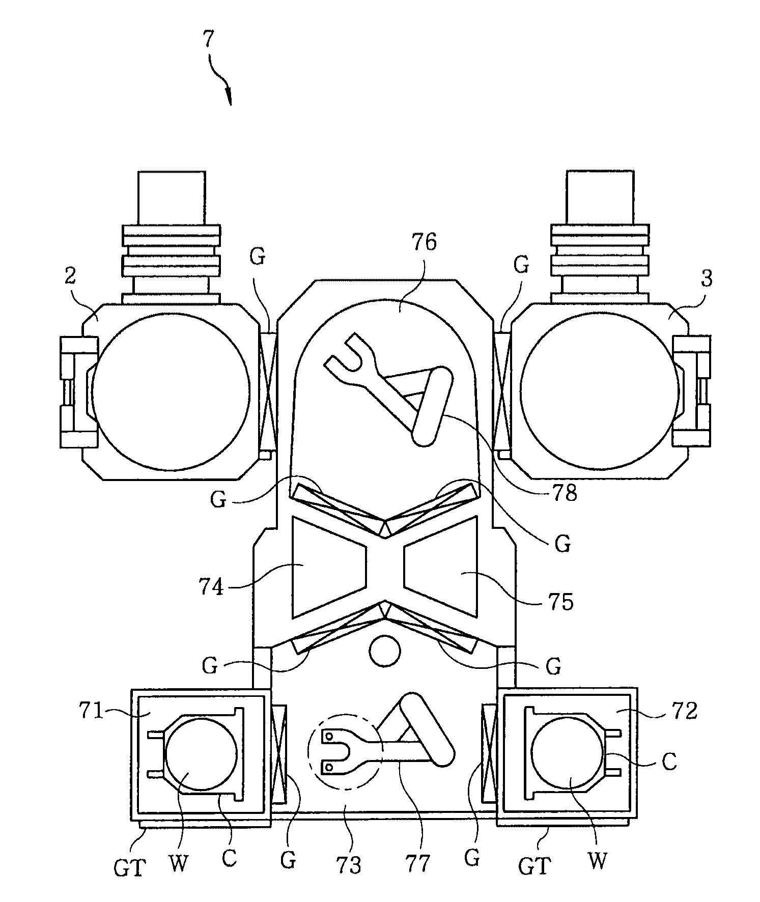
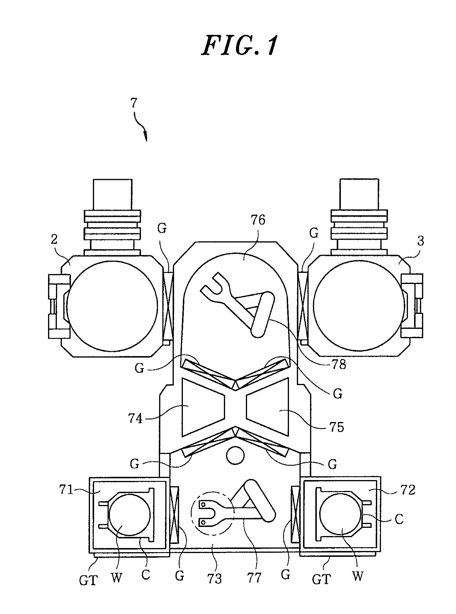
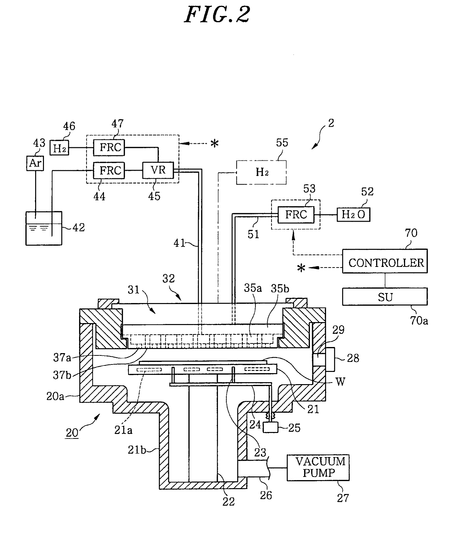
A semiconductor device, which suppresses formation of an organic impurity layer and has excellent adhesiveness to a copper film and a metal to be a base, is manufactured. A substrate (wafer W) coated with a barrier metal layer (base film) 13 formed of a metal having a high oxidation tendency, such as titanium, is placed in a processing chamber. At the time of starting to supply water vapor or after that, a material gas containing an organic compound of copper (for instance, Cu(hfac)TMVS) is supplied, and a copper film is formed on the surface of the barrier metal layer 13 whereupon the oxide layer 13a is formed by the water vapor. Then, heat treatment is performed on the wafer W, and the oxide layer 13a is converted into an alloy layer 13b of a metal and copper which constitute the barrier metal layer 13.

Description

FIELD OF THE INVENTION[0001]The present invention relates to a technology for manufacturing a semiconductor device having excellent adhesiveness between a copper film for wiring and a base film thereof.BACKGROUND OF THE INVENTION[0002]In a recent wiring technology, copper lines are replacing aluminum lines to improve performance of a semiconductor device. In a manufacturing process of the semiconductor device, a technology for forming a copper film on a surface of a semiconductor wafer (hereinafter, referred to as a “wafer”) is important. A chemical vapor deposition method (hereinafter, referred to as “CVD”) using a copper organic compound as a material has been known as one of technologies for forming a copper film on the wafer.[0003]When a copper film is formed on the wafer by using CVD, a copper organic compound, e.g., Cu(hexafluoroacetylacetonate) trimethylvinylsilane (hereinafter, referred to as “Cu(hfac)TMVS”) serving as a source gas is supplied to a processing chamber in a va...

Claims


Application Information

Patent Timeline
Patent Type & Authority Applications(United States)
IPC IPC(8): H01L21/3205C23C16/54
CPCC23C16/0281C23C16/18H01L21/28556H01L21/76877H01L21/76855H01L21/76858H01L21/76867H01L21/76843H01L21/3205H01L21/285H01L21/324H01L23/52
Inventor KOJIMA, YASUHIKOIKEDA, TAROHATANO, TATSUO
Owner TOKYO ELECTRON LTD
Learn More