Posterior spinal fastener and method for using same

a technology of anterior spinal cord and fastener, which is applied in the field of anterior spinal cord fastener and method for using same, can solve the problems of transpedicular screw failure, transpedicular screw failure within the bone, and pedicle perforation

Active Publication Date: 2010-01-21
TOTAL CONNECT SPINE
View PDF37 Cites 114 Cited by
  • Summary
  • Abstract
  • Description
  • Claims
  • Application Information

AI Technical Summary

Problems solved by technology

Unfortunately, transpedicular screws usually fail either by breaking at the connection between the transpedicular screw and the assembly to which it is attached, or by failure of the transpedicular screw to bone interface.
A transpedicular screw can fail within the bone for multiple reasons, including osteoporotic nature of the bone, lack of fill within the pedicle, infection and / or pseudoarthrosis of the fusion mass.
In order to achieve better fixation, larger transpedicle screws are sometimes used, which may result in a fracture or perforation of the pedicle resulting in nerve root or spinal cord injury.
At the upper end of instrumented construct, most transpedicle screws have to violate the normal facet joint, which may lead to an increase risk of degeneration of the adjacent disk.
At the upper end of the instrumented construct, traditional transpedicle screw technique may violate the bordering facet joint creating additional mechanical driving force for adjacent segment disease and the potential for further surgery over time in that adjacent segment.
This is a disadvantage in osteoporotic, pathologic, or low density bone where there is less for the screws to anchor to and a decrease in the pullout strength of the screw, especially in shear.
The transpedicle screw may also penetrate the pedicle wall possibly injuring the exiting nerve root.
This penetration may significantly risk neurological or vascular structures.
An additional problem with current devices is safety.
Therefore, a very small margin of error exists anatomically when forming the scaffold function of spinal instrumentation with pedicle screws fixed to each thoracic vertebral level.
In other words, the technique of delivery of pedicle screws in the thoracic and lumbar spine carries inherent risk to the geometry of design of the pedicle and screw and the vector of placement into the vertebra.
This particular problem often occurs in the medial and / or inferior quadrant of the pedicle, where the nerve route most closely contacts the pedicle.
When a thoracic pedicle screw is placed, medial deviation can impale the spinal cord and imprecise placement may strike the anterior vascular structures with disastrous results.

Method used


Image

  • Posterior spinal fastener and method for using same
  • Posterior spinal fastener and method for using same
  • Posterior spinal fastener and method for using same

Examples


Embodiment Construction

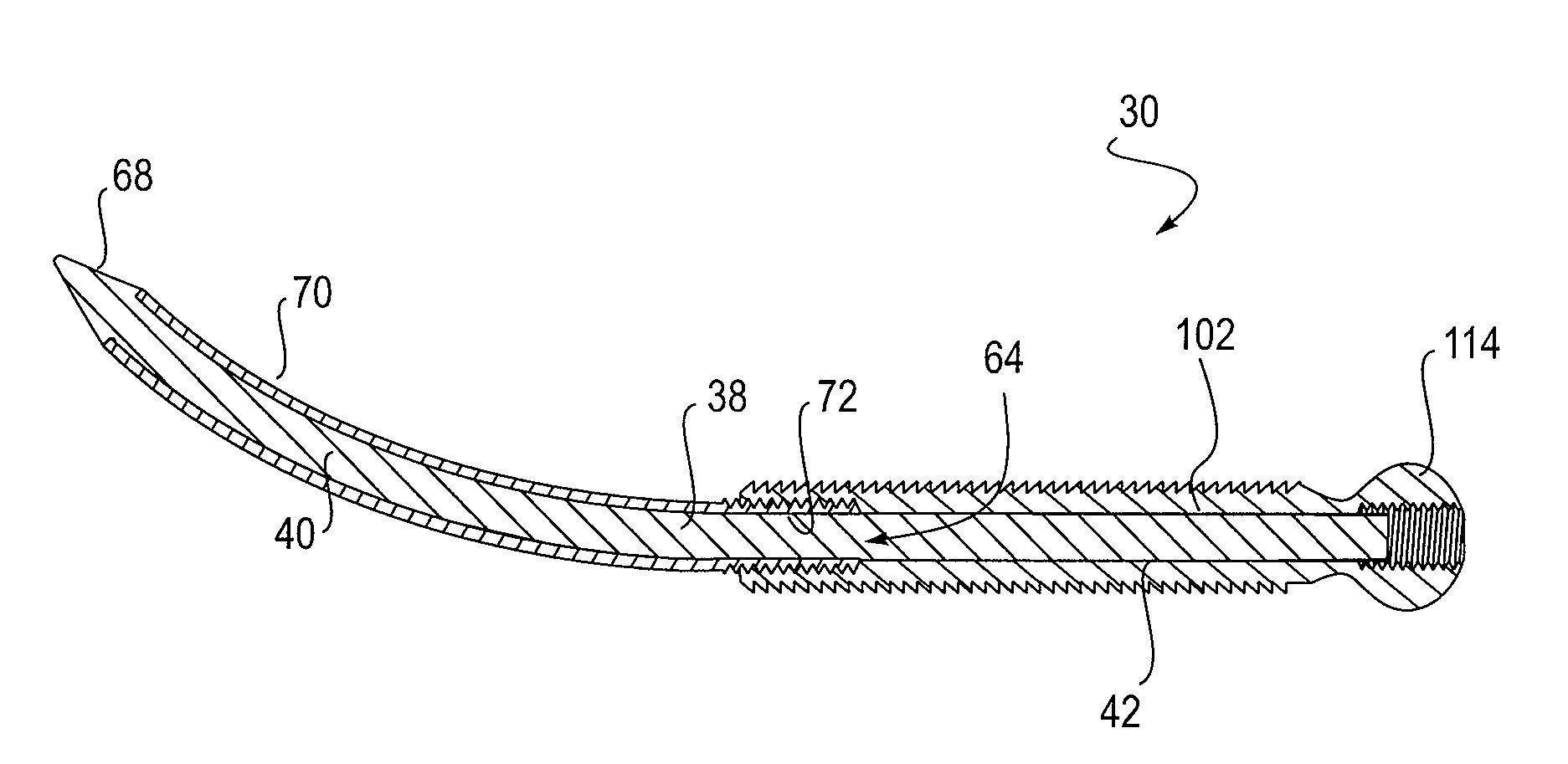
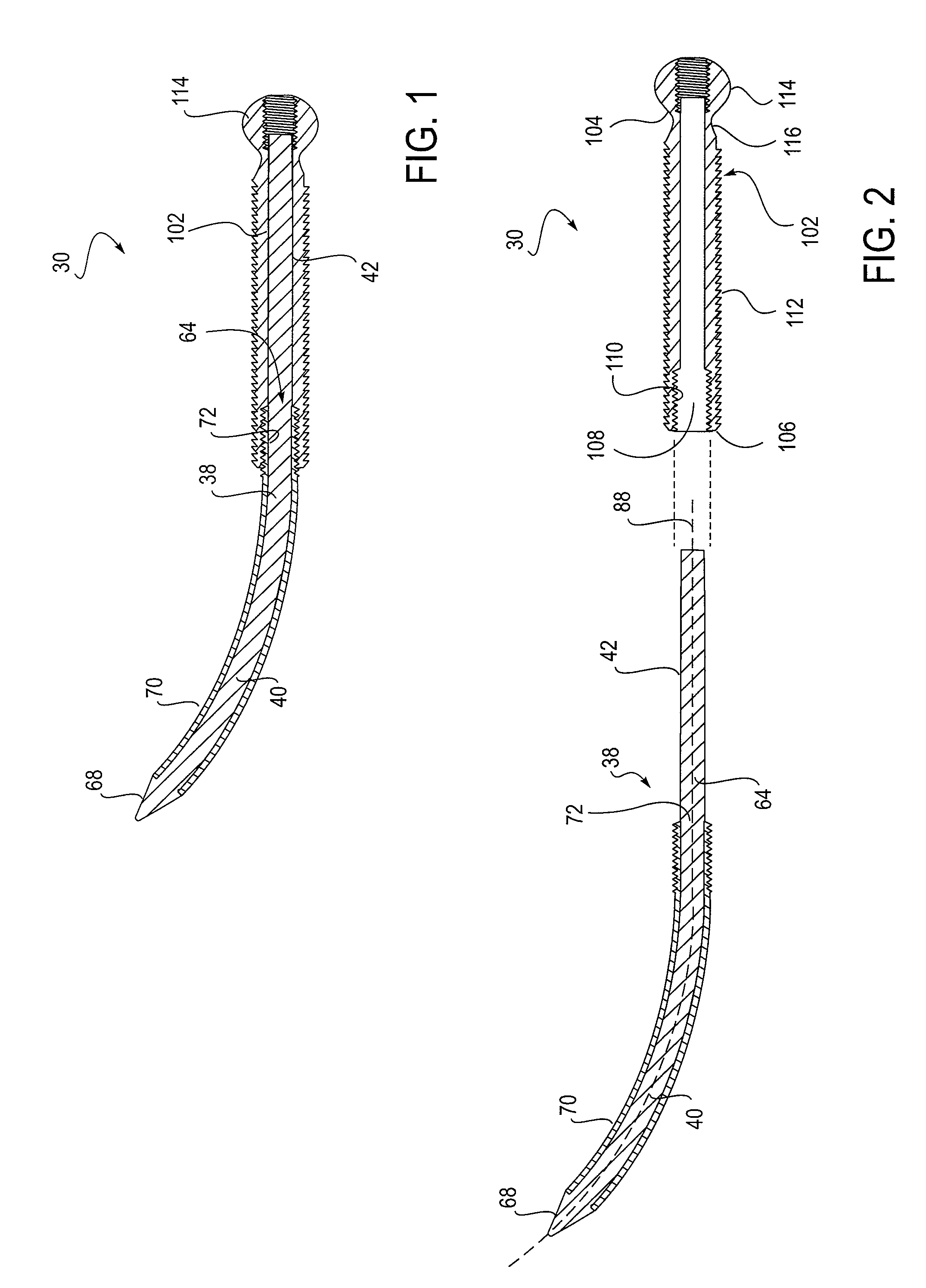
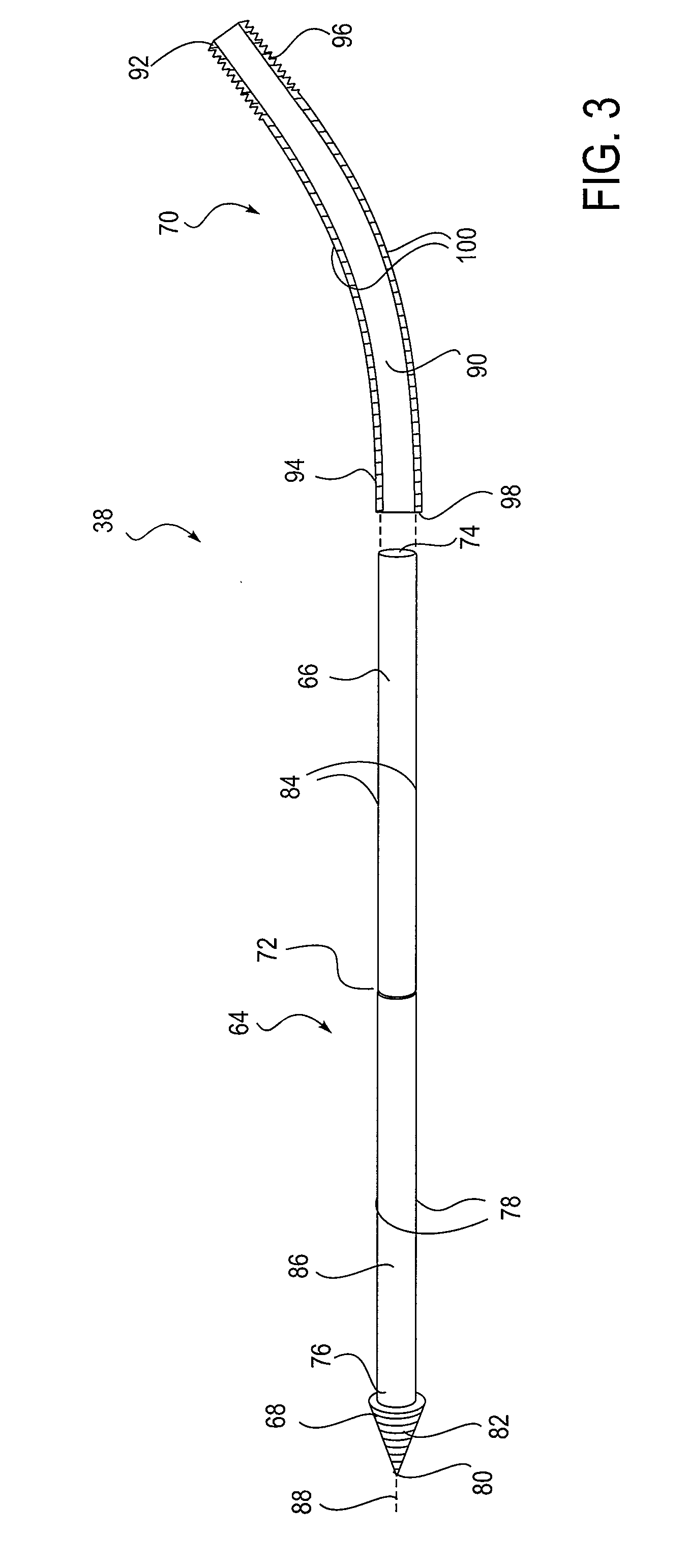
[0039]The invention is generally directed to posterior spinal fasteners, and a system for stabilizing adjacent vertebra in a mammalian spine. As a non-limiting example, the invention may be used in association with a bone graft. Hardware is placed in the spine which will immobilize the spine while the bone solidifies or becomes one large bone mass. The system includes a curved fastener or post that can be inserted as either a transpedicular, transfacet or a laminopedicular fastening device to the posterior portion of the spine, and preferably, at or near the posterior spinal elements found in the vertebra.

[0040]More preferably, a posterior spinal fastener 30 for insertion into a vertebra 32 of a mammalian body having posterior elements 34 and a vertebral body 36 is provided (See FIGS. 1-15). The posterior spinal fastener 30 generally includes an elongate member 38 adapted for insertion into the vertebra 32. The elongate member 38 has an anterior portion 40 and a posterior portion 42...


PUM


Abstract

A posterior spinal fastener is disclosed for insertion into a vertebra of a mammalian body, the vertebra having posterior elements and a vertebral body. The fastener includes an elongate member adapted for insertion into the vertebra. The elongate body has an anterior portion and a posterior portion. The anterior portion is arcuate in shape for placement in the vertebral body. The posterior portion has a length so as to be accessible at the posterior elements of the vertebra when the anterior portion is disposed in the vertebral body. A method of use of the posterior spinal fastener is also disclosed, in which the posterior spinal fastener is introduced into the vertebra at the posterior elements and arcuately extended into the vertebral body.

Description

CROSS-REFERENCE TO RELATED APPLICATION[0001]This application claims priority to U.S. Provisional Patent Application Ser. No. 61 / 046,762 filed Apr. 21, 2008 which is incorporated herein by this reference.SCOPE OF THE INVENTION[0002]The present invention relates to surgical fasteners, and in particular to posterior spinal fasteners.BACKGROUND[0003]As is known, spinal fusions may be indicated when there is a deformity of the spine, instability of the spine, a damaged intervertebral disk, trauma, tumor, pain, infection and / or degeneration of the spine. A number of posterior spinal fixation methods are available to instrument the spine for stabilization purposes and to allow for a fusion to occur. Commonly used devices include transpedicle and facet screws. Many transpedicle screw systems that stabilize the spine are dependent upon the pullout strength of a non-curved transpedicle screw for fixation stability. Unfortunately, transpedicular screws usually fail either by breaking at the co...

Claims


Application Information

Patent Timeline
Patent Type & Authority Applications(United States)
IPC IPC(8): A61B17/86
CPCA61B17/864A61B17/866A61B17/8685A61B17/1642A61B17/1671A61B17/8625A61B17/7001A61B17/7035A61B17/7049A61B17/7098A61B17/70
Inventor MATITYAHU, AMIR M.MCCLELLAN, ROBERT TRIGGDILLIN, WILLIAM H.
Owner TOTAL CONNECT SPINE
Why Eureka
Try Eureka