
Controlled Freeze Zone Tower

a technology of freeze zone and control tower, which is applied in the direction of liquefaction, lighting and heating apparatus, and separation processes, etc., can solve the problems of increasing the scrutiny of the practice of venting cosub>2/sub>, affecting the effect of surface area, and affecting the separation process

Inactive Publication Date: 2010-01-28
FIELER ELEANOR R +3
View PDF100 Cites 108 Cited by
  • Summary
  • Abstract
  • Description
  • Claims
  • Application Information

AI Technical Summary

Benefits of technology

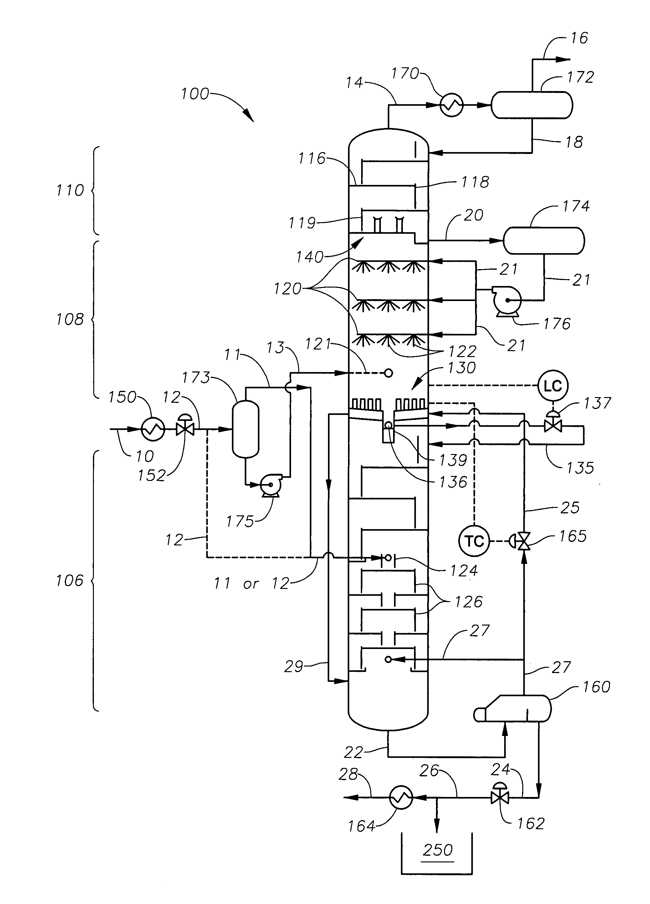
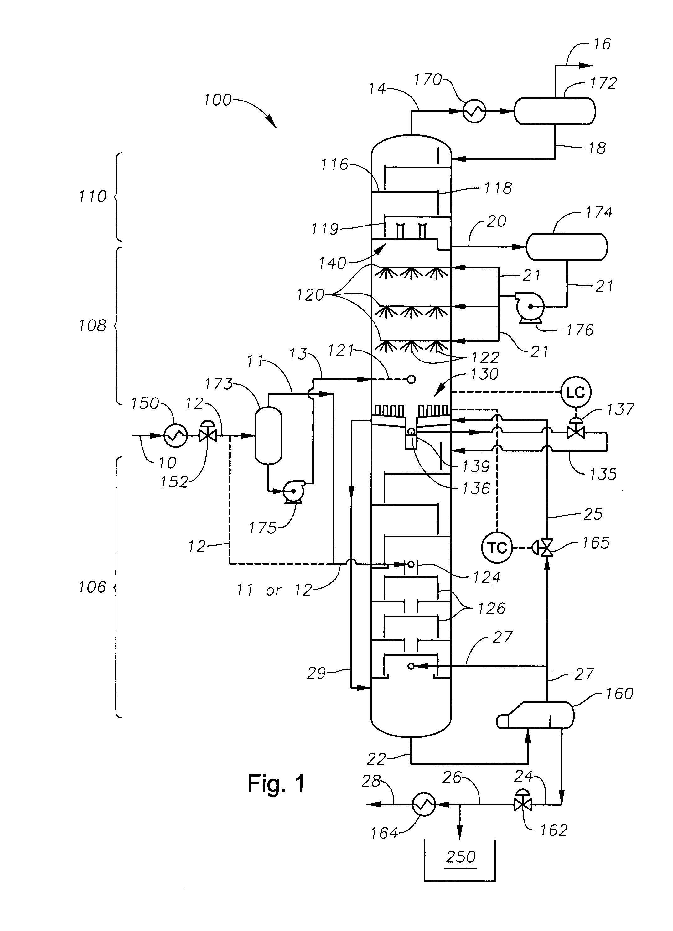
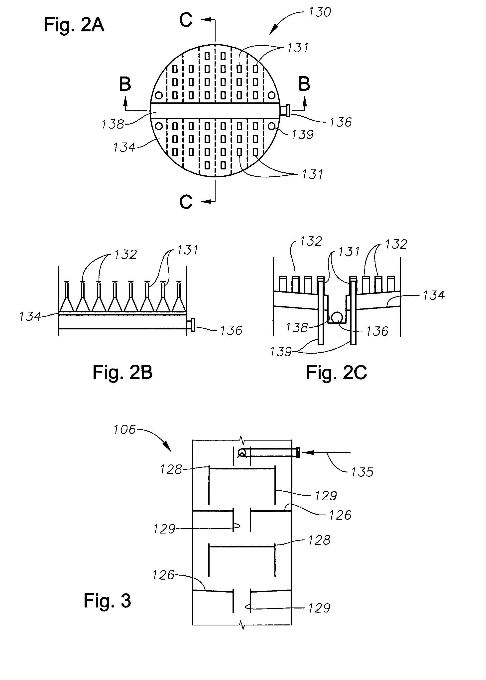
[0021]Preferably, the melt tray in the lower stripping section includes a base, and a plurality of chimneys extending upward from the base. The melt tray preferably also includes a cap over each chimney. In one aspect, the base defines a generally radial base extending across the inner diameter of the distillation tower, with the base having first and second opposite sides sloped inwardly towards an intermediate portion of the base. A downcomer is then disposed within the intermediate portion of the base to receive liquids collected by the melt tray. In another aspect, the base has a generally sinusoidal or other corrugated profile to increase its surface area.

Problems solved by technology

The separation process creates an issue as to the disposal of the separated contaminants.
However, in some areas (such as the Caspian Sea region), additional elemental sulfur production is undesirable because there is a limited market.
However, the practice of venting CO2 is coming under greater scrutiny, particularly in countries that have ratified the Kyoto protocol which requires the reduction of CO2 emissions.
For “highly sour” streams, that is, production streams containing greater than about 15% to about 20% CO2 and H2S, it can be particularly challenging to design, construct, and operate a process that can economically separate these contaminants from the desired hydrocarbons.
One problem which has been encountered in the practice of cryogenic gas processing relates to the relatively low temperature at which CO2 phase changes into a solid.

Method used


Image

  • Controlled Freeze Zone Tower
  • Controlled Freeze Zone Tower
  • Controlled Freeze Zone Tower

Examples


Embodiment Construction

Definitions

[0038]As used herein, the term “mass transfer device” refers to any object that receives fluid and passes it to another object, such as through gravitational flow. One non-limiting example is a tray for stripping out certain fluids. A grid packing is another example.

[0039]The term “baffle” means any object that interferes with the direct gravitational flow of liquid.

Description of Specific Embodiments

[0040]FIG. 1 presents a schematic view of a cryogenic distillation tower of the present invention, in one embodiment. The cryogenic distillation tower is referred to generally as 100. The tower 100 may be interchangeably referred to herein as a “cryogenic distillation tower,” a “column,” a “CFZ column,” or a “splitter tower.”

[0041]The cryogenic distillation tower 100 of FIG. 1 receives an initial fluid stream 10. The fluid stream 10 is comprised of production gasses. Typically, the fluid stream represents a dried gas stream from a wellhead (not shown), and contains about 65% ...


PUM


Abstract

A cryogenic distillation tower is provided for the separation of a fluid stream containing at least methane and carbon dioxide. The cryogenic distillation tower has a lower stripping section, an upper rectification section, and an intermediate spray section. The intermediate spray section includes a plurality of spray nozzles that inject a liquid freeze zone stream. The nozzles are configured such that substantial liquid coverage is provided across the inner diameter of the intermediate spray section. The liquid freeze zone stream generally includes methane at a temperature and pressure whereby both solid carbon dioxide particles and a methane-enriched vapor stream are formed. The tower may further include one or more baffles below the nozzles to create frictional resistance to the gravitational flow of the liquid freeze zone stream. This aids in the breakout and recovery of methane gas. Additional internal components are provided to improve heat transfer and to facilitate the breakout of methane gas.

Description

CROSS REFERENCE TO RELATED APPLICATIONS[0001]This application claims the benefit of U.S. Provisional Application No. 60 / 881,395, filed 19 Jan. 2007.[0002]This application is related to U.S. Provisional No. 60 / 881,391, entitled Integrated Controlled Freeze Zone (CFZ) Tower and Dividing Wall (DWC) for Enhanced Hydrocarbon Recovery, filed 19 Jan. 2007, by Vikram Singh, Edward J. Grave, Paul Scott Northrop, and Narasimhan Sundaram.BACKGROUND OF THE INVENTION[0003]1. Field of the Invention[0004]The present invention relates to the field of fluid separation. More specifically, the present invention relates to the cryogenic separation of carbon dioxide from a hydrocarbon fluid stream.[0005]2. Background of the Invention[0006]The production of hydrocarbons from a reservoir oftentimes carries with it the incidental production of non-hydrocarbon gases. Such gases include contaminants, such as hydrogen sulfide (H2S) and carbon dioxide (CO2). When H2S and CO2 are produced along with a hydrocarb...

Claims


Application Information

Patent Timeline
IPC IPC(8): F25J3/00
CPCB01D3/166Y02C10/12B01D3/26F25J3/0209F25J3/0233F25J3/0266F25J2200/02F25J2200/74F25J2200/90F25J2205/04F25J2205/20F25J2215/04F25J2220/66F25J2240/02F25J2240/40F25J2260/80F25J2270/12F25J2270/60F25J2280/40F25J2290/40F25J2290/72B01D3/24Y02C20/40F25J3/00
Inventor FIELER, ELEANOR RGRAVE, EDWARD J.NORTHROP, PAUL SCOTTYEH, NORMAN K.
Owner FIELER ELEANOR R
Learn More