Air-Coupled Acoustic Thermography for In-Situ Evaluation

a technology in-situ evaluation, which is applied in the field of air-coupled acoustic thermography, can solve the problems of insufficient sensitivity of the inspection system, difficulty in determining the size/shape of the defect, and current approaches that suffer from one or more drawbacks, etc., and achieves enhanced sensitivity and/or repeatability

Inactive Publication Date: 2010-01-28
NASA
View PDF25 Cites 38 Cited by
  • Summary
  • Abstract
  • Description
  • Claims
  • Application Information

AI Technical Summary

Benefits of technology

[0010]Another object of the present invention is to provide an acoustic thermography system and method having a high-degree of flaw / damage sensitivity.
[0012]In accordance with the present invention, an acoustic thermography system and method are provided. A housing is configured for thermal, acoustic and infrared radiation shielding. For in-situ applications, the housing has an open side adapted to be sealingly coupled to a surface region of a structure such that an enclosed chamber filled with air is defined by the housing and the surface region. At least one acoustic source supported by the housing is positioned to direct an acoustic wave therefrom through the air in the enclosed chamber and towards the surface region. To activate and control each acoustic source, a pulsed signal is applied thereto. The pulsed signal is defined by a time series of pulses having specified frequency, amplitude and phase. An infrared imager is focused on the surface region to detect a thermal image of the surface region. A data capture device records the thermal image in synchronicity with each pulse of the pulsed signal such that a time series of thermal images is generated. For enhanced sensitivity and / or repeatability, sound and / or vibrations at the surface region can be used in feedback control of the pulsed signal that is applied to the acoustic sources.

Problems solved by technology

Since these structures are prone to moisture absorption through minute skin imperfections or damages, the inspection system must be sensitive.
Unfortunately, current approaches suffer from one or more drawbacks.
However, it is difficult to determine defect size / shape through interpretation of fringe pattern data produced by this approach.
The continual need to attach / detach the reference blocks adds time and cost to the inspection regimen, poses risks of damage to the structure's surface, and presents problems for inspection repeatability.
However, this system is not sensitive enough for inspection of composite sandwich structures.

Method used


Image

  • Air-Coupled Acoustic Thermography for In-Situ Evaluation
  • Air-Coupled Acoustic Thermography for In-Situ Evaluation
  • Air-Coupled Acoustic Thermography for In-Situ Evaluation

Examples


Embodiment Construction

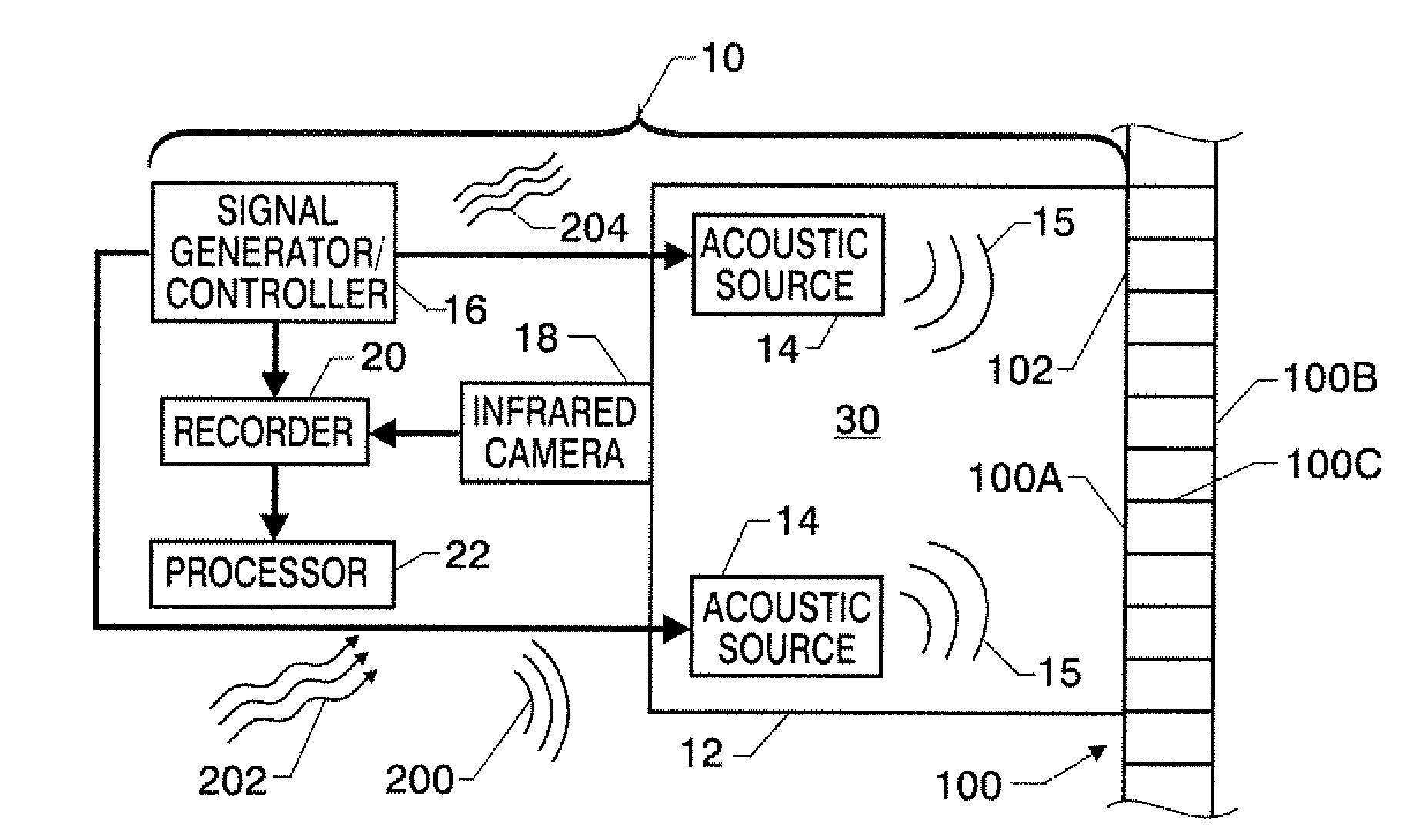
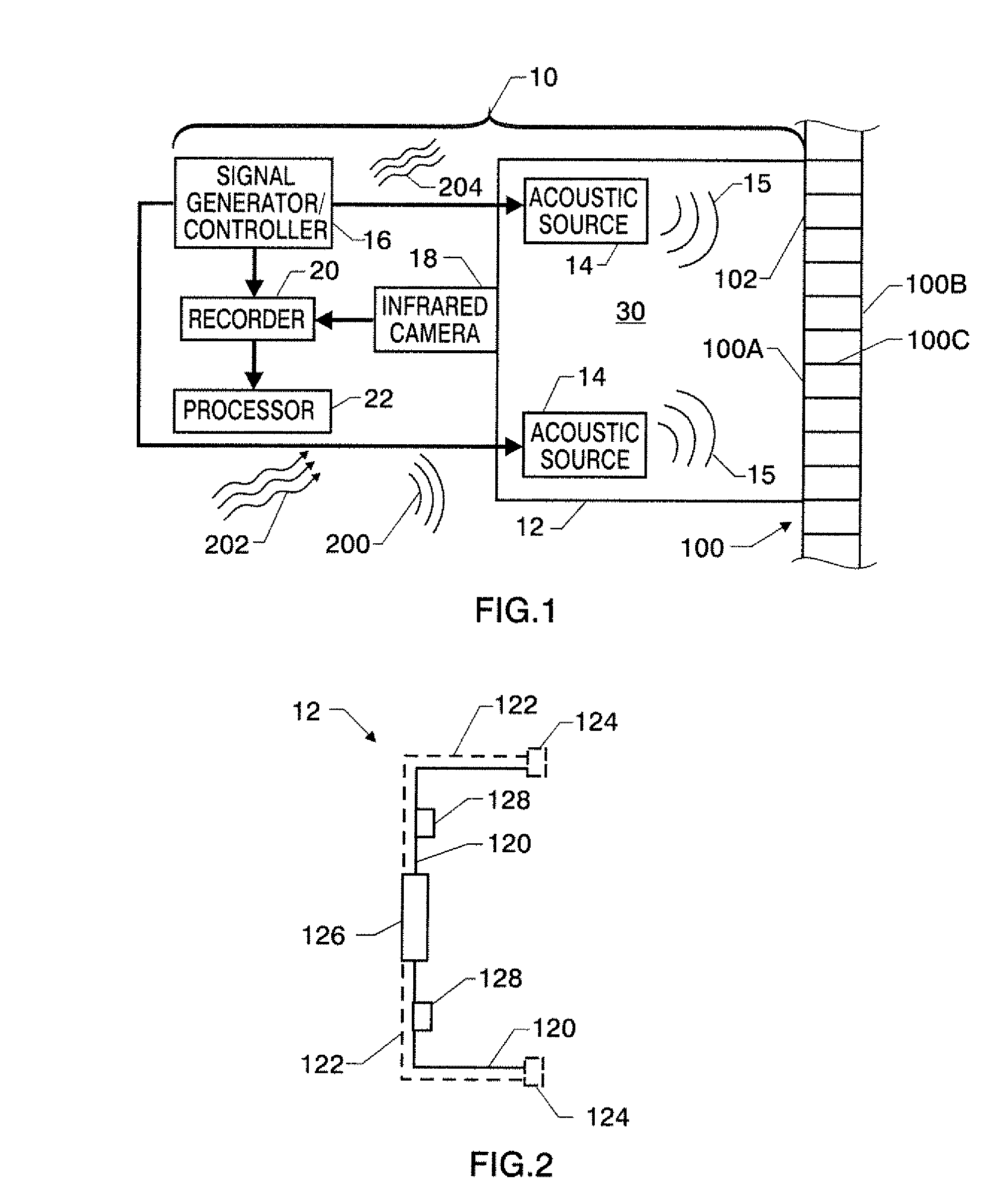
[0017]Referring now to the drawings and more particularly to FIG. 1, an in-situ air-coupled acoustic thermography system in accordance with an embodiment of the present invention is shown and is referenced generally by numeral 10. System 10 is positioned adjacent to a portion 102 of a structure 100. By way of example, portion 102 is a composite sandwich structure having facing skins 100A and 100B sandwiching a lightweight core 100C such as a honeycomb. However, it is to be understood that the particular construction of the structure is not a limitation of the present invention. In addition, facing skin 100A need not present a flat planar surface as system 10 can be readily configured to work on a contoured surface.

[0018]In the illustrated embodiment, acoustic thermography system 10 includes a housing 12, one or more acoustic sources 14, a signal generator / controller 16, an infrared camera 18, and a recorder 20. In general, system 10 produces and couples acoustic energy to portion 10...


PUM

PropertyMeasurementUnit
thermalaaaaaaaaaa
frequencyaaaaaaaaaa
phaseaaaaaaaaaa

Abstract

Acoustic thermography uses a housing configured for thermal, acoustic and infrared radiation shielding. For in-situ applications, the housing has an open side adapted to be sealingly coupled to a surface region of a structure such that an enclosed chamber filled with air is defined. One or more acoustic sources are positioned to direct acoustic waves through the air in the enclosed chamber and towards the surface region. To activate and control each acoustic source, a pulsed signal is applied thereto. An infrared imager focused on the surface region detects a thermal image of the surface region. A data capture device records the thermal image in synchronicity with each pulse of the pulsed signal such that a time series of thermal images is generated. For enhanced sensitivity and / or repeatability, sound and / or vibrations at the surface region can be used in feedback control of the pulsed signal applied to the acoustic sources.

Description

ORIGIN OF THE INVENTION[0001]The present invention was made by employees of the United States Government and may be manufactured and used by or for the Government of the United States of America for governmental purposes without the payment of any royalties thereon or therefor.BACKGROUND OF THE INVENTION[0002]1. Field of the Invention[0003]This invention relates to acoustic thermography. More specifically, the invention is a system and method for air-coupled acoustic thermography that can be used for in-situ evaluation of structures.[0004]2. Description of the Related Art[0005]Aircraft structures are increasingly being made from advanced composite sandwich structures typically defined by a lightweight core (e.g., a honeycomb) faced with thin composite skins. These structures are relatively inexpensive, lightweight, repairable, and can be molded into complex shapes. From time-to-time, aircraft incorporating these composite sandwich structures must be inspected for damage In particula...

Claims


Application Information

Patent Timeline
Patent Type & Authority Applications(United States)
IPC IPC(8): G01J5/02G01N29/00
CPCG01N25/72G01N29/343G01N29/228
Inventor ZALAMEDA, JOSEPH N.WINFREE, WILLIAM P.YOST, WILLIAM T.
Owner NASA
Why Eureka
Try Eureka