[0006]The invention is based on the concept of introducing an indentation, in particular an elongated indentation, which serves as a solder barrier and at least regionally prevents the solder from flowing past the circumferential edge of the securing portion or the contact segment, into the securing portion, preferably a
copper or
copper alloy, of the segment support piece and / or into the underside, oriented toward the securing portion, of the contact segments, which are preferably made from a carbon-
graphite mixture. This kind of solder barrier indentation can easily be embossed or stamped in the securing portion in the production of the segment support piece. The depth and width of the solder barrier indentation should be dimensioned such that it can hold enough liquid solder to prevent a solder from spilling over from the solder barrier indentation.
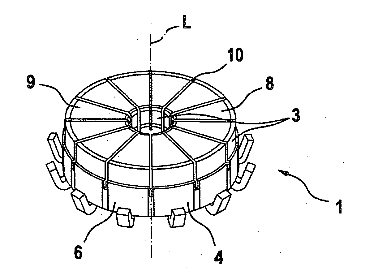
[0008]If the commutator is embodied as a flat commutator with a level
brush running surface, and the securing portion is formed by a radial portion of the segment support piece, it is advantageous to dispose the solder barrier indentation at least in a radially outer region of the securing portion, to prevent an escape of liquid solder on the circumferential side of the commutator.
[0009]To achieve as large as possible a
soldering face and hence good strength and electrical
conductivity of the connections of the contact segments and securing portions, it is provided in an advantageous refinement of the invention that the solder barrier indentation is disposed with a slight
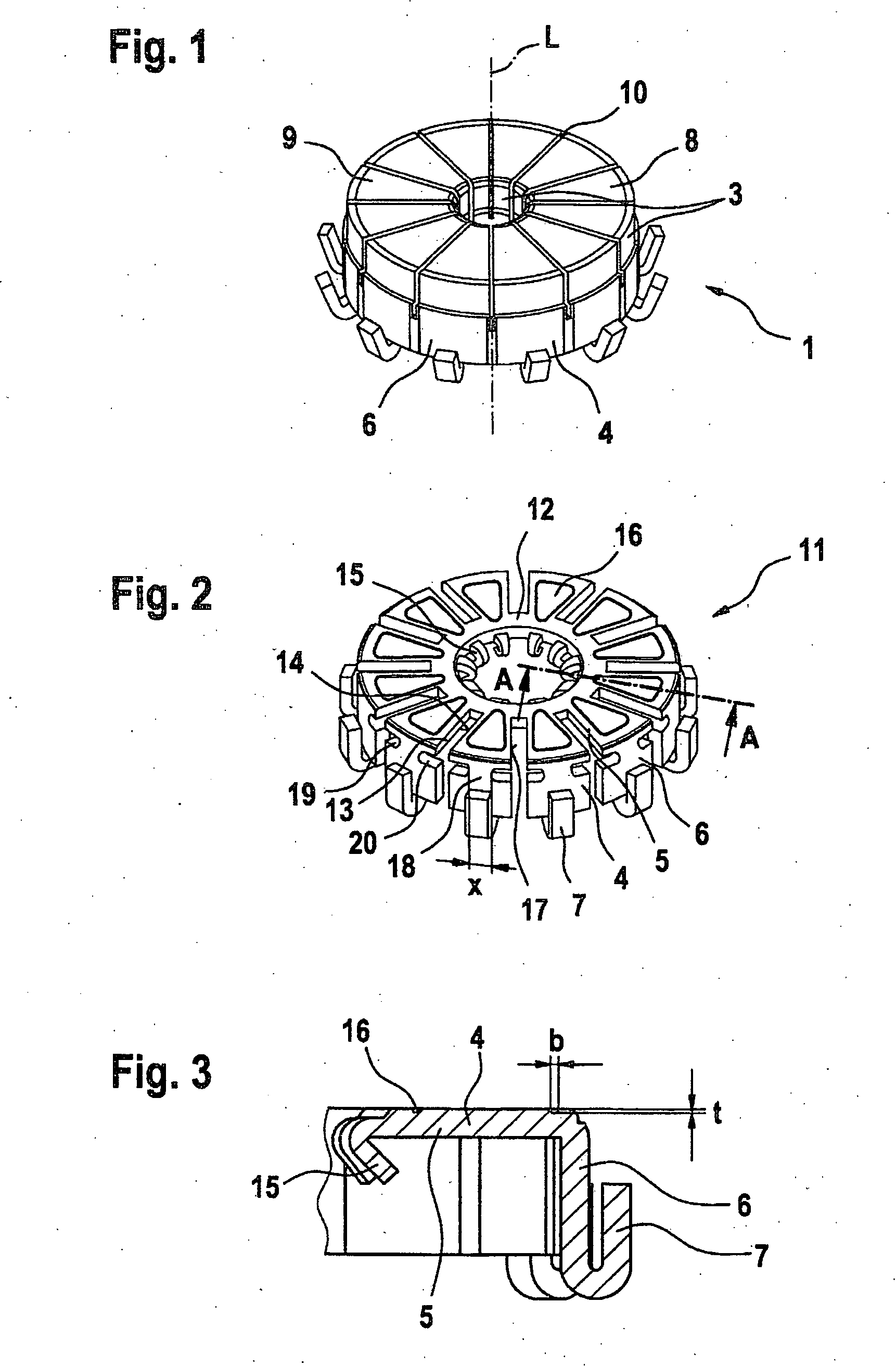
peripheral spacing on the underside of the contact segment and / or on the top side of the securing portion. The solder barrier indentation is preferably embodied as a circumferentially closed, trenchlike indentation.
[0010]To protect the soldered connection between one contact segment and the associated securing portion against harmful thermal influence, especially in a hot
staking process for securing a winding wire on the winding connection hook of the associated segment support piece, it is advantageously provided in a feature of the invention that, in a region between the winding connection hook and the securing portion, a heat barrier region with a reduced cross-sectional area is provided. As a result of the reduction of the effective cross-sectional area, the flow of heat-from the winding connection hook in the direction of the securing portion and thus in the direction of the soldered connection is worsened, and as a result, adverse effects of the hot
staking process on the soldered connection are advantageously avoided.
[0013]Still further-improved heat protection is provided by an expedient refinement of the invention. In the production of the commutator, a
metal stamped and bent part, particularly of
copper, is used, which has segment support pieces disposed side by side in the circumferential direction. Preferably, one solder barrier indentation is introduced into each of these segment support pieces. Each segment support piece has one winding connection hook and one securing portion for the fixation of a contact segment. Each two
adjacent segment support pieces are connected to one another via a preferably curved rib oriented in the circumferential direction. Otherwise, there is only an air gap between the
adjacent segment support pieces. Taken as a whole, all the ribs form a circular-annular connection. In the invention, it is now provided that this circular-annular connection is spaced apart as far as possible from the winding connection hooks, preferably in the region of the free end, remote from the winding connection hooks, of the securing portions. The reason is accordingly as follows. In the course of further production of the commutator, a contact disk is first soldered to the securing portions. Next, the component comprising the metal stamped and bent part and the contact disk, which is preferably of carbon or a carbon-
graphite mixture, is partially
extrusion-coated with an insulating material, preferably a pressed material, in particular a thermosetting plastic with reinforcing elements, such as glass fibers or
glass fiber beads. The metal sides facing toward one another of the segment support pieces are likewise
extrusion-coated in the process. To attain an electrical insulation of the segment support pieces from one another, the contact disk must be subdivided in a further step into individual contact segments. Moreover, all of the connecting ribs between the segment support pieces must be removed. This is done for instance by a sawing operation, in which the width of the saw or the saw blade is preferably less than the air gap between two
adjacent segment support pieces. After the connecting ribs have been severed, two free metal faces, that is, metal faces that are not insulated from the hub body, remain on each segment support piece, and by way of them, heat can “flow into” the segment support piece or its securing portion especially well and thus have an
adverse effect on the soldered connection with the associated contact segment. Because the spacing according to the invention of the connecting ribs (and thus of the free metal faces) from the winding connection hooks that are heated during the hot
staking process is as great as possible, only a minimal amount of heat is introduced via these free faces into the associated securing portions, which has an advantageous effect on the soldered connection between the securing portion and the contact segment.

