Power supply system and vehicle including the same

a power supply system and power supply technology, applied in the direction of battery/fuel cell control arrangement, secondary cell servicing/maintenance, hybrid vehicles, etc., can solve the problems of electric power taken out of the battery, insufficient disclosure of output current control, and susceptible to temperature, so as to improve the running performance of the vehicle, improve the energy efficiency, and improve the effect of energy saving

Active Publication Date: 2010-01-28
TOYOTA JIDOSHA KK
View PDF11 Cites 40 Cited by
  • Summary
  • Abstract
  • Description
  • Claims
  • Application Information

AI Technical Summary

Benefits of technology

[0046]According to the vehicle above, it is ensured that temperature increase control of the power storage unit will have been completed by the time of start of the vehicle, while ensuring improvement in energy efficiency, depending on a state of the vehicle, Consequently, running performance of the vehicle can be i

Problems solved by technology

On the other hand, as the power storage unit stores electric energy utilizing electrochemical action, charge/discharge characteristics thereof are susceptible to a temperature.
Though the heating-up device disclosed in Japanese Patent Laying-Open No. 11-26032 carries out control such that the output current of the battery greater than the required current flows when an instruction is issued from at least one of the unlock detection means, the timer means, and the input means described above, this publication does not pr

Method used


Image

  • Power supply system and vehicle including the same
  • Power supply system and vehicle including the same
  • Power supply system and vehicle including the same

Examples


Embodiment Construction

[0062]An embodiment of the present invention will be described hereinafter in detail with reference to the drawings. It is noted that the same or corresponding elements have the same reference characters allotted in the drawings.

Configuration of Vehicle

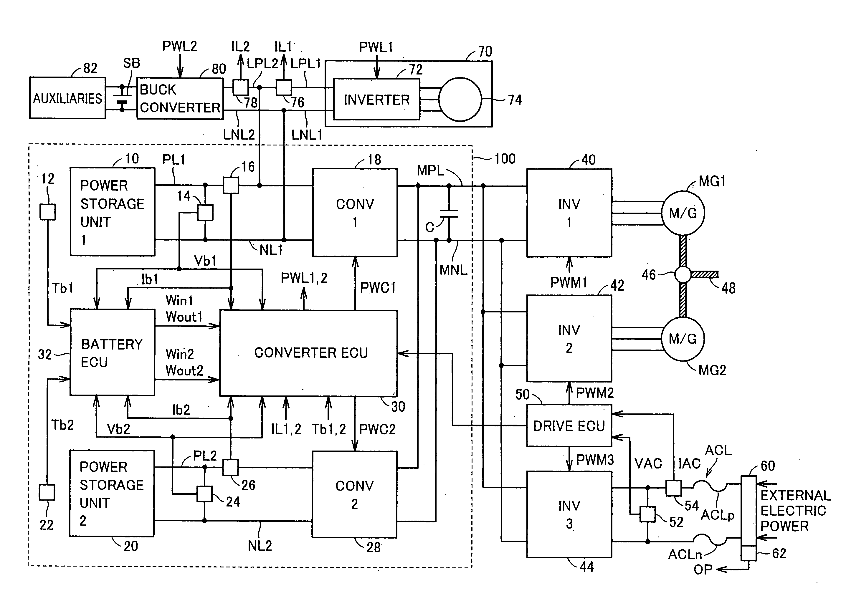
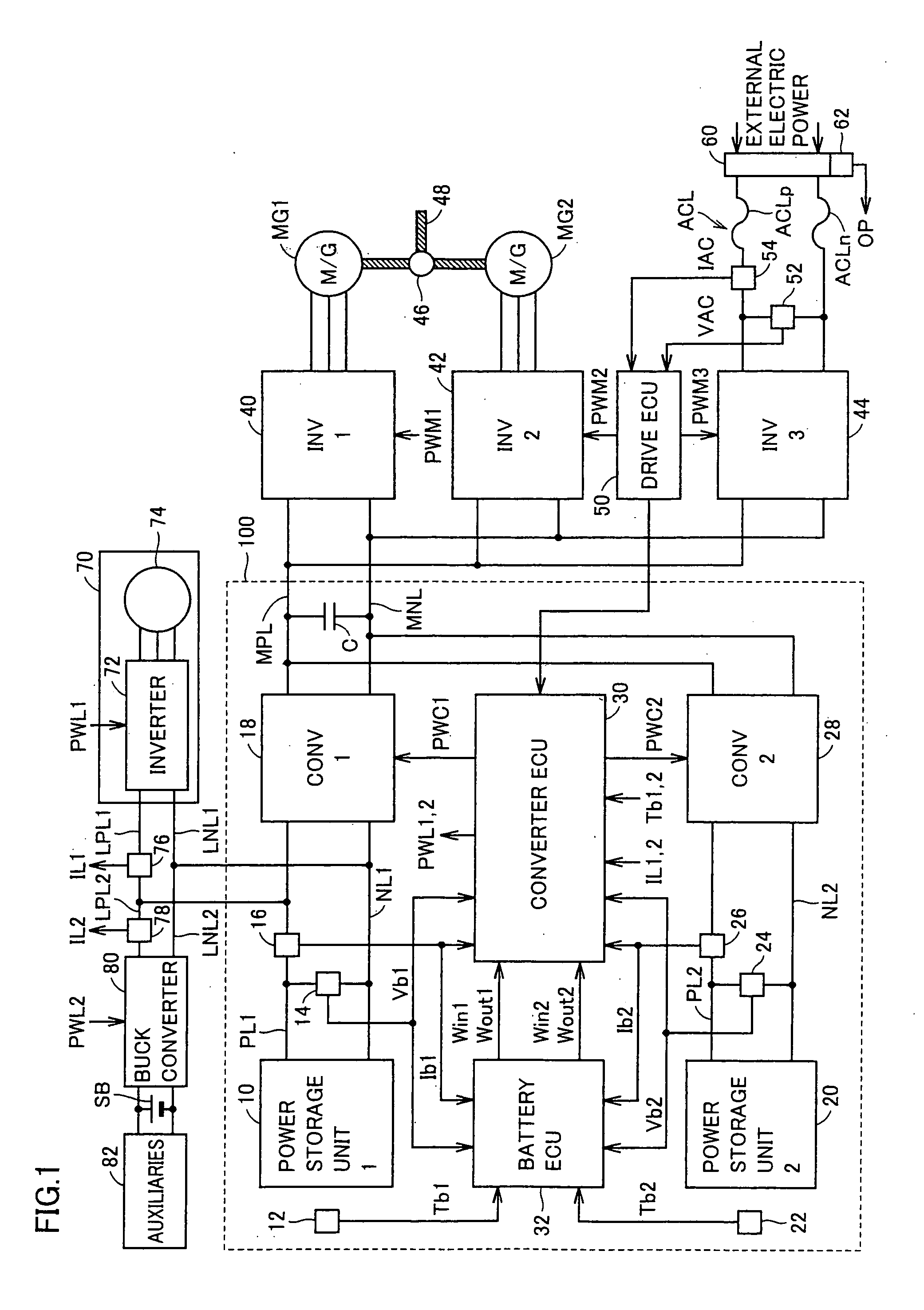
[0063]FIG. 1 is a schematic configuration diagram showing a substantial part of a vehicle including a power supply system 100 according to an embodiment of the present invention.

[0064]Referring to FIG. 1, the vehicle includes power supply system 100, a first inverter (INV1) 40, a second inverter (INV2) 42, a third inverter (INV3) 44, motor-generators MG1, MG2, and a drive ECU (Electrical Control Unit) 50.

[0065]Inverters 40, 42, motor-generators MG1, MG2, and drive ECU 50 configure a drive force generation unit generating drive force of the vehicle. The present embodiment illustrates an example where the drive force generation unit serves as a “load device”. Namely, the vehicle runs by transmitting to wheels (not shown), drive force ge...


PUM


Abstract

A converter ECU Obtains a temperature increase start signal indicating start of temperature increase of a power storage unit from each sensor and ECU provided in a vehicle. In addition, the converter ECU obtains allowable electric power of the power storage unit from a battery ECU and obtains a power storage unit temperature from a temperature detection unit. When any of the obtained power storage unit temperatures is lower than a corresponding temperature lower limit value, the converter ECU generates a temperature increase instruction for the power storage unit of which temperature is lower than the corresponding temperature lower limit value, based on the temperature increase start signal. In addition, the converter ECU selects one control mode from among a plurality of control modes set in advance, based on the generated temperature increase instruction, and sets that mode as the control mode for a converter.

Description

TECHNICAL FIELD[0001]The present invention relates to a power supply system and a vehicle including the same, and more particularly to a power supply system having a plurality of power storage units and a vehicle including the same.BACKGROUND ART[0002]Recently, considering environmental issues, attention has been paid to a vehicle employing a motor as a drive power source, such as an electric vehicle, a hybrid vehicle and a fuel cell vehicle. Such a vehicle includes a power storage unit implemented, for example, by a secondary battery or an electric double layer capacitor for supplying electric power to the motor, and converting kinetic energy to electric energy during regenerative braking and storing such electric power.[0003]In such a vehicle employing the motor as the drive force source, in order to enhance acceleration performance and running performance such as travel distance, greater charge / discharge capacity of the power storage unit is desired. Here, a configuration where a...

Claims


Application Information

Patent Timeline
IPC IPC(8): H02J7/00B60L3/00B60L11/18H01M10/44H01M10/60H01M10/615H01M10/625H01M10/633H01M10/637
CPCB60L1/003B60L3/0046B60L3/0053B60L11/1861B60L11/1875B60L2260/56Y02T90/34H01M10/5006H01M10/5016H01M10/5026Y02T10/7005Y02T10/7044Y02T10/705H01M10/44H01M10/625H01M10/615H01M10/637B60L58/12B60L58/27B60L58/26Y02T10/70Y02E60/10Y02T90/40
Inventor ICHIKAWA, SHINJIISHIKAWA, TETSUHIRO
Owner TOYOTA JIDOSHA KK
Why Eureka
Try Eureka