Wind Turbine Blade Position Determination System

a technology of wind turbine blade position and position determination, which is applied in the direction of propellers, engine control parameters, water-acting propulsive elements, etc., can solve the problems of high cost, complex mounting and maintenance, and equipment that needs to be very robust, and achieves low cost

Inactive Publication Date: 2010-01-28
VESTAS WIND SYST AS
View PDF7 Cites 56 Cited by
  • Summary
  • Abstract
  • Description
  • Claims
  • Application Information

AI Technical Summary

Benefits of technology

[0035]Passive position indicative data is in accordance with the present invention understood as a signal that comprises no position indicative data per se, but the signal becomes position indicative when received at the receiver, i.e. the position is determined at the receiver on the basis of the signal sent from the transmitter. This may be a very simple and short burst, e.g. a radio or ultrasonic signal.
[0036]It is a very advantageous feature according to an embodiment of the invention that the wind turbine blade comprises nothing but a simple transmitter. This means that no complex circuits, receiving units or the like must be implemented into the wind turbine blade which is the case in the prior art systems. These must both have means for receiving a signal, means for processing and means for re-transmitting the position indicative data. This entails in addition that the transmitter may easily and at low cost be retrofitted to existing wind turbine blades.

Problems solved by technology

A problem in relation with the prior art is that GPS receivers have to be mounted in the blades and consequently resulting in that mounting and maintenance may become quite complex and costly.
A further problem of the above-mentioned prior art is that it requires that data and / or signal processing is performed in the blade, for the purpose of determining a relative or absolute position of the blade or blade portions of the blade.
A further problem related to mounting of relative sensitive electronics such as a GPS receiver in the blade is that equipment needs to be very robust to e.g. resist relative large difference in temperature and mechanic stress caused by vibrations and rotation of the blade.

Method used


Image

  • Wind Turbine Blade Position Determination System
  • Wind Turbine Blade Position Determination System
  • Wind Turbine Blade Position Determination System

Examples


Embodiment Construction

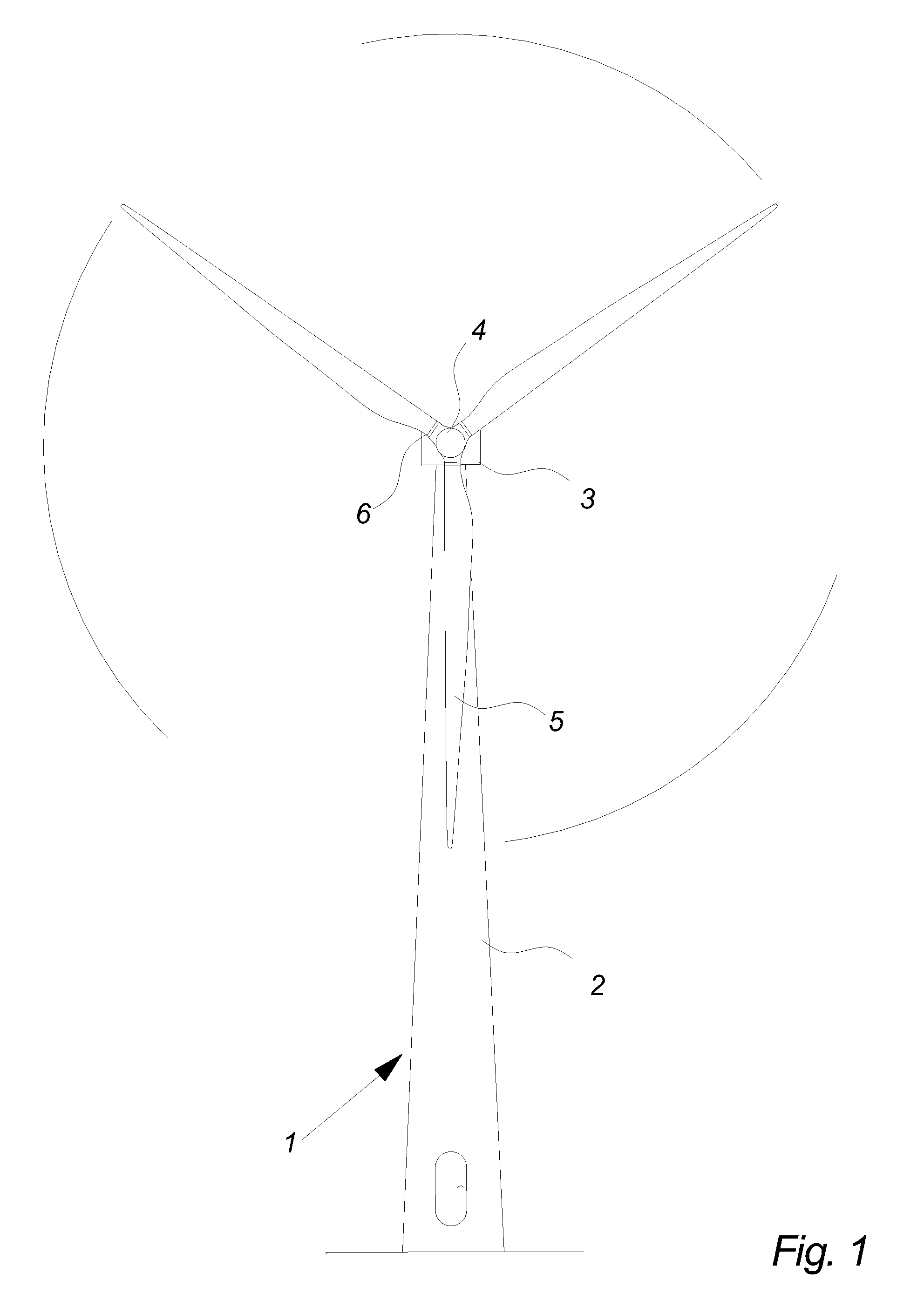
[0079]FIG. 1 illustrates a modern wind turbine 1. The wind turbine 1 comprises a tower 2 positioned on a foundation. A wind turbine nacelle 3 with a yaw mechanism is placed on top of the tower 2.

[0080]A low speed shaft extends out of the nacelle front and is connected with a wind turbine rotor through a wind turbine hub 4. The wind turbine rotor comprises at least one rotor blade e.g. three rotor blades 5 as illustrated.

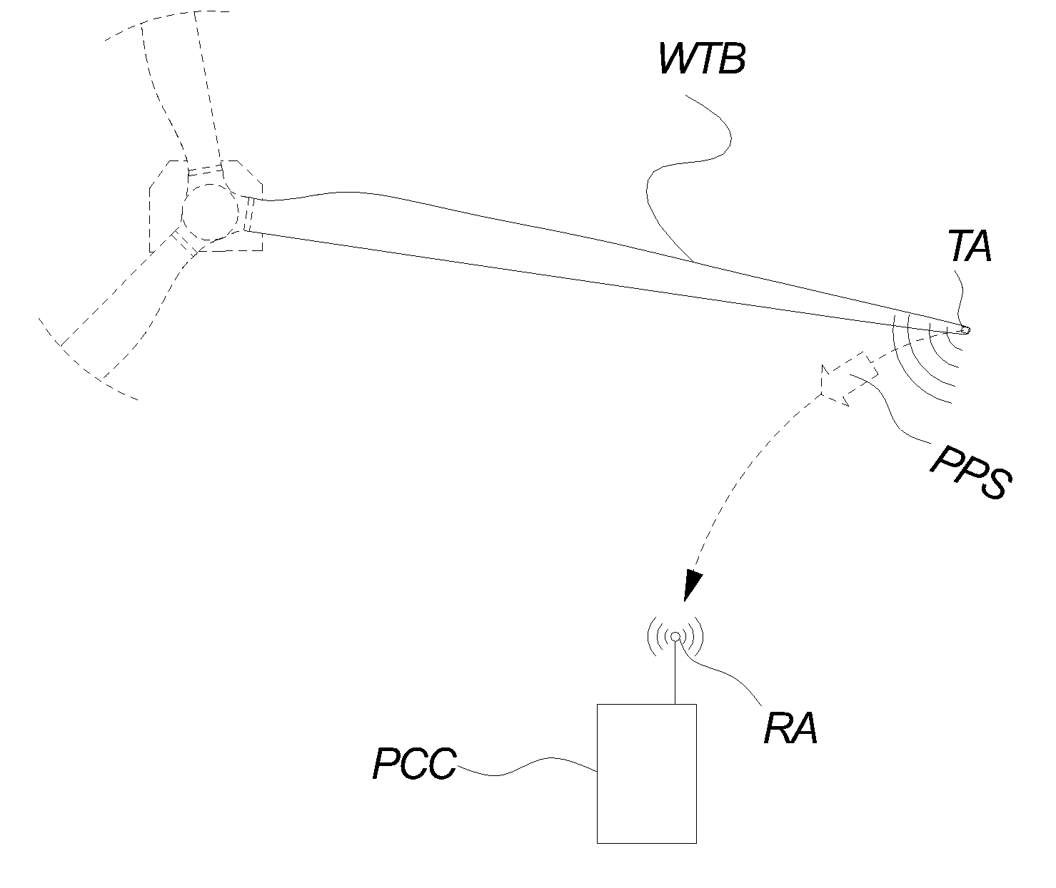
[0081]FIG. 2 illustrates a system for wireless transmission of a so-called passive position signal PPS according to an embodiment of the invention.

[0082]The term passive position signal PPS is introduced to avoid confusion between the signal reflecting the position of the wind turbine blade in the geometric space and other signals mentioned throughout this application. Hence, passive position signal PPS defines a signal transmitted from the transmitter arrangement TA attached to the wind turbine blade throughout the rest of the detailed description.

[0083]The figure i...


PUM


Abstract

A system for determining the position of at least a part of a wind turbine blade by wireless transmission of a signal includes a transmitter arrangement attached to a wind turbine blade, a receiving arrangement, and at least one position calculation computer, wherein the signal is wirelessly transmitted from the at least one transmitter arrangement to the receiving arrangement, and wherein the position calculation computer calculates position indicative data on the basis of the signal received by the receiving arrangement and wherein the position indicative data indicates a position of at least a part of the wind turbine blade.

Description

CROSS-REFERENCE TO RELATED APPLICATIONS[0001]The present application is a continuation of pending International patent application PCT / DK2008 / 000125 filed on Mar. 31, 2008 which designates the United States and claims priority from Danish patent application PA 2007 00499 filed on Mar. 30, 2007, the content of which is incorporated herein by reference.FIELD OF THE INVENTION[0002]The invention relates to a system determining the blade position of a wind turbine.BACKGROUND OF THE INVENTION[0003]In relation to optimizing the operation of wind turbines, many surveillance technologies have been disclosed in order to anticipate errors and in relation to optimize the energy production of the wind turbine generators.[0004]International patent application WO 2005 / 068834 relates to a method for determining the position of position indicators placed on the blades of a wind turbine by means of position indicators that can be GPS receivers receiving signal from three GPS satellites, enabling that...

Claims


Application Information

Patent Timeline
Patent Type & Authority Applications(United States)
IPC IPC(8): F03D11/00
CPCF03D7/047F03D11/0091F05B2270/326Y02E10/723F05B2270/80Y02E10/721Y02E10/722F05B2270/33F03D17/00Y02E10/72F03D7/04
Inventor SANDVAD, INGEMANN HVAS
Owner VESTAS WIND SYST AS
Why Eureka
Try Eureka