Ultrasonic diagnostic apparatus

a diagnostic apparatus and ultrasonic technology, applied in the field of ultrasonic diagnostic apparatus, can solve the problems of insufficient transmission sound pressure, 131440 does not disclose the reduction of circuit size, and insufficient s/n ratio in the region of transmission sound pressure, so as to reduce circuit size, secure image quality, and increase the effect of circuit siz

Inactive Publication Date: 2010-01-28
FUJIFILM CORP
View PDF3 Cites 25 Cited by
  • Summary
  • Abstract
  • Description
  • Claims
  • Application Information

AI Technical Summary

Benefits of technology

[0016]The present invention has been achieved in view of the above-mentioned problems. A purpose of the present invention is to provide an ultrasonic diagnostic apparatus, even with a reduced circuit size, capable of securing image quality equal to an apparatus having a larger circuit size.
[0018]According to the one aspect of the present invention, the selected ultrasonic transducers transmit the ultrasonic beams at plural times and the ultrasonic transducers in the plural different apertures respectively receive the ultrasonic echoes generated by the ultrasonic beams transmitted at the plural times, and thereby, the ultrasonic diagnostic apparatus, even with a reduced circuit size, capable of securing image quality equal to an apparatus having a larger circuit size can be provided.

Problems solved by technology

In order to improve resolving power in ultrasonic imaging, channels of the ultrasonic transducers and transmitting and receiving circuits may be increased, however, that causes cost rise.
Also, JP-A-8-131440 does not disclose reduction of the circuit size while maintaining image quality.
On the other hand, according to JP-P2003-126088A, a broad transmission beam is used, and a sufficient S / N ratio is not achieved in a region where transmission sound pressure is insufficient.

Method used


Image

  • Ultrasonic diagnostic apparatus
  • Ultrasonic diagnostic apparatus
  • Ultrasonic diagnostic apparatus

Examples


first embodiment

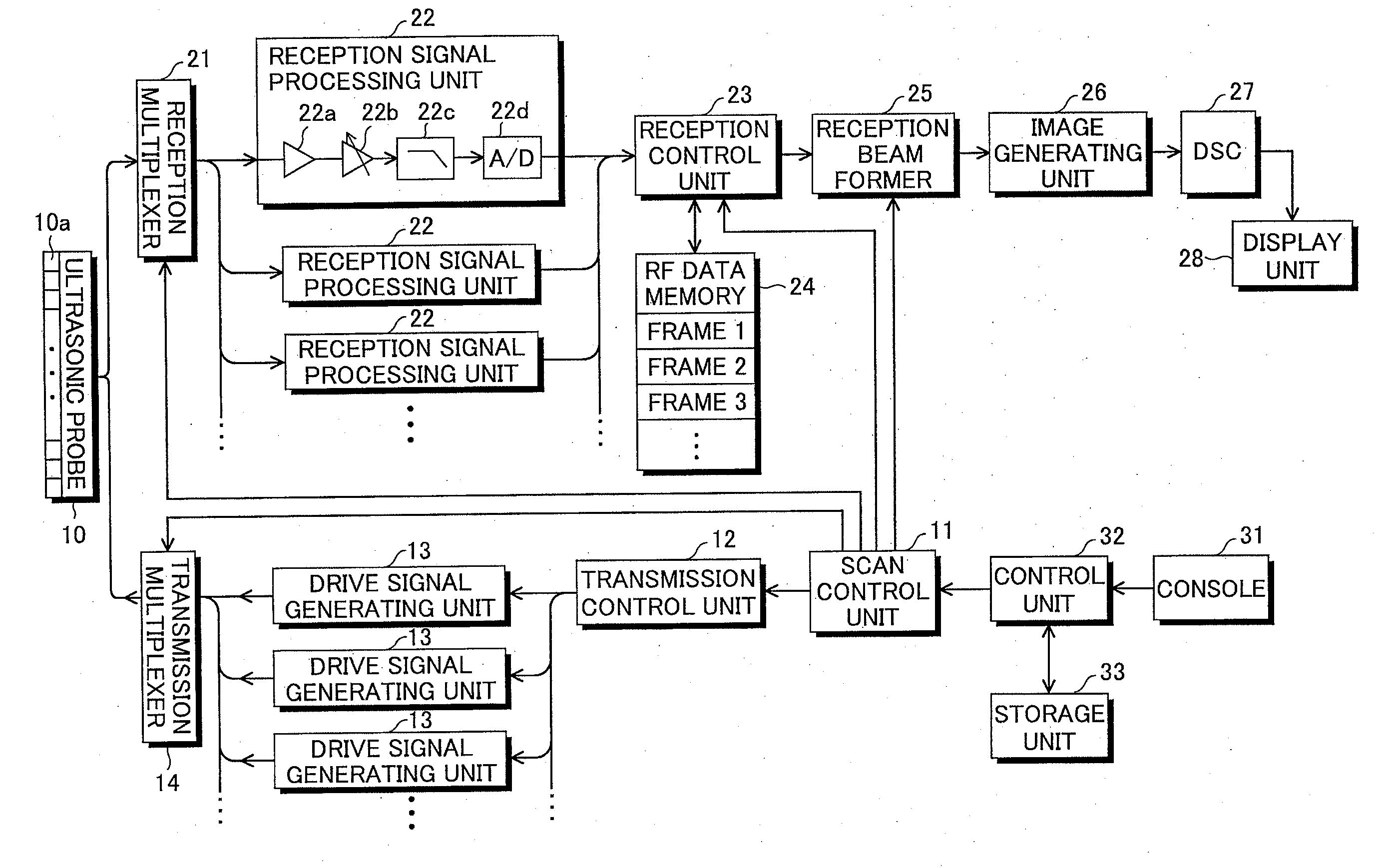
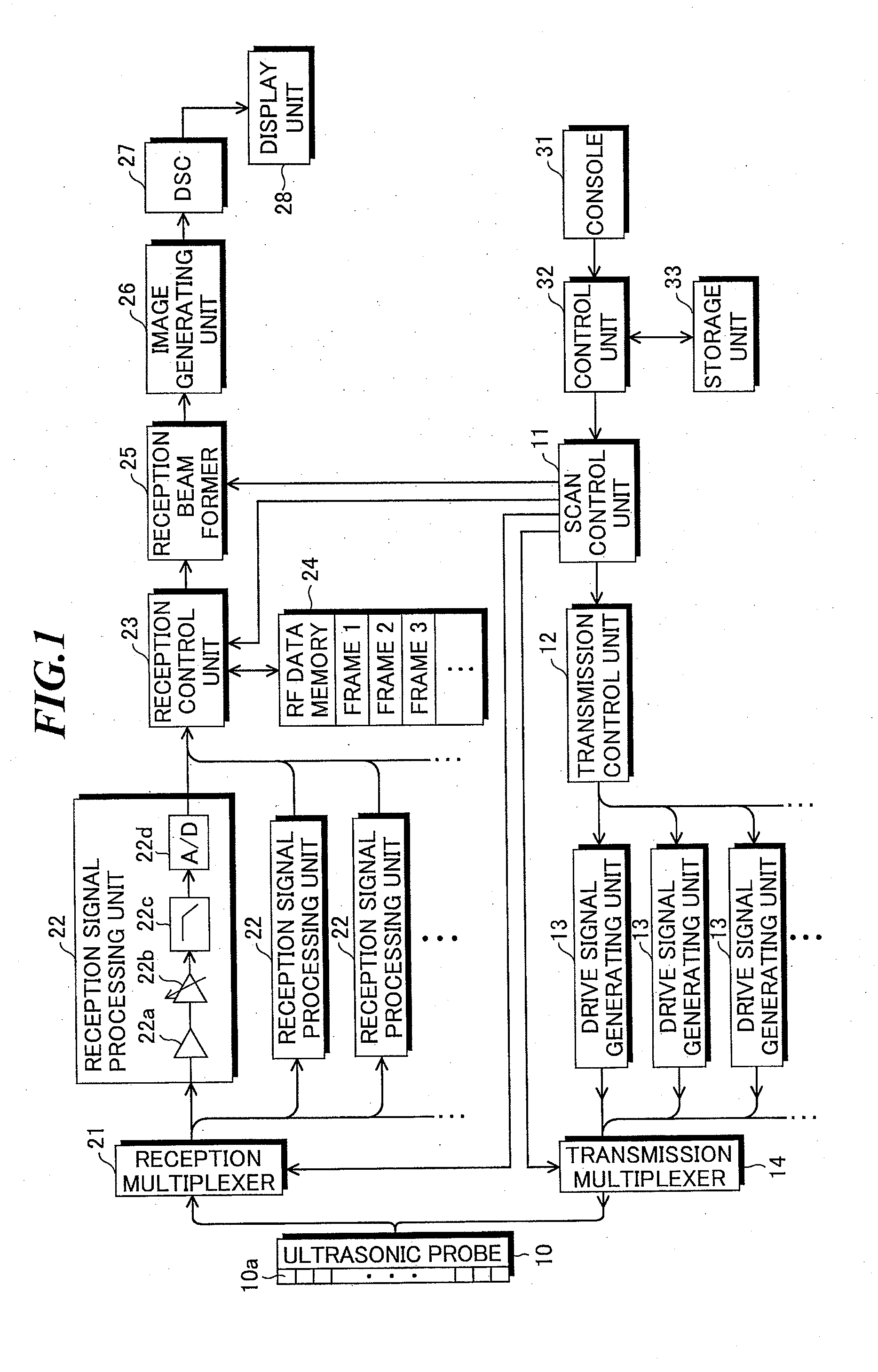
[0030]FIG. 1 is a block diagram showing a configuration of an ultrasonic diagnostic apparatus according to the present invention. The ultrasonic diagnostic apparatus includes an ultrasonic probe 10, a scan control unit 11, a transmission control unit 12, a drive signal generating unit 13, a transmission multiplexer (MUX) 14, a reception multiplexer (MUX) 21, a reception signal processing unit 22, a reception control unit 23, an RF data memory 24, a reception beam former 25, an image generating unit 26, a DSC 27, a display unit 28, a console 31, a control unit 32, and a storage unit 33.

[0031]The ultrasonic probe 10 includes plural ultrasonic transducers (hereinafter, also referred to as “elements”) 10a that transmit ultrasonic waves to an object to be inspected according to applied drive signals, and receive ultrasonic echoes propagating from the object to output reception signals. These ultrasonic transducers 10a are one-dimensionally or two-dimensionally arranged to form a transduc...

second embodiment

[0051]Next, the present invention will be explained.

[0052]FIG. 4 is a block diagram showing a configuration of an ultrasonic diagnostic apparatus according to the second embodiment of the present invention. The ultrasonic diagnostic apparatus according to the second embodiment is provided with a control signal distributing unit 15 and one multiplexer (MUX) 16 in place of the transmission multiplexer 14 and the reception multiplexer 21 in the ultrasonic diagnostic apparatus according to the first embodiment as shown in FIG. 1.

[0053]FIG. 5 shows a connection example of the control signal distributing unit and the multiplexer as shown in FIG. 4. In FIG. 5, ultrasonic transducers of channels (CH.) 1-16 are shown. Further, the multiplexer 16 includes eight switches SW1-SW8. For example, one of the ultrasonic transducer of CH. 1 and the ultrasonic transducer of CH. 9 is selected by the switch SW1, and one of the ultrasonic transducer of CH. 2 and the ultrasonic transducer of CH. 10 is sel...

third embodiment

[0065]Next, the present invention will be explained.

[0066]FIG. 8 is a block diagram showing a configuration of an ultrasonic diagnostic apparatus according to the third embodiment of the present invention. In the ultrasonic diagnostic apparatus according to the third embodiment of the present invention, plural ultrasonic transducers 10a are arranged along at least one direction, and the ultrasonic probe 10 further includes a movement mechanism 10b for moving the plural ultrasonic transducers 10a in the at least one direction.

[0067]In the third embodiment, large sized ultrasonic transducers (elements) 10a are used, and the element pitch is also large. Generally, the element pitch is 0.5λ to 1λ (λ is a wavelength of ultrasonic waves). In the embodiment, the element pitch may be set to about 1λ to 2λ, and the case where the element pitch is 2λ will be explained as below. When ultrasonic waves having a frequency of 3.5 MHz are used in an ultrasonic probe for abdomen, given that the acou...


PUM


Abstract

An ultrasonic diagnostic apparatus, even with a reduced circuit size, capable of securing image quality equal to that having a larger circuit size. The apparatus includes: a drive signal generating unit for supplying drive signals to selected ultrasonic transducers; a reception signal processing unit for processing reception signals outputted from ultrasonic transducers in a selected aperture; a control unit for controlling the drive signal generating unit such that ultrasonic beams are transmitted at plural times, and sequentially storing the reception signals obtained by ultrasonic transducers in plural different apertures receiving ultrasonic echoes generated by the ultrasonic beams transmitted at the plural times, in a memory; a reception beam former for performing reception focusing processing on the reception signals corresponding to the plural different apertures to generate sound ray signals; and an image signal generating unit for generating an image signal based on the sound ray signals.

Description

CROSS-REFERENCE TO RELATED APPLICATION[0001]The present application claims priority from Japanese Patent Application No. 2008-193654 filed on Jul. 28, 2008, the contents of which are incorporated herein by reference in their entirety.BACKGROUND OF THE INVENTION[0002]1. Field of the Invention[0003]The present invention relates to an ultrasonic diagnostic apparatus for imaging organs, bones, and so on within a living body by transmitting and receiving ultrasonic waves to generate ultrasonic images to be used for diagnoses.[0004]2. Description of a Related Art[0005]In medical fields, various imaging technologies have been developed for observation and diagnoses within an object to be inspected. Especially, ultrasonic imaging for acquiring interior information of the object by transmitting and receiving ultrasonic waves enables image observation in real time and provides no exposure to radiation unlike other medical image technologies such as X-ray photography or RI (radio isotope) scin...

Claims


Application Information

Patent Timeline
Patent Type & Authority Applications(United States)
IPC IPC(8): A61B8/14
CPCA61B8/14G01S7/52034G01S7/52047G10K11/346G01S15/8927G01S15/8997G01S7/52085
Inventor SATOH, TOMOO
Owner FUJIFILM CORP
Why Eureka
Try Eureka