
Emission control system and method

Inactive Publication Date: 2010-02-04
GENERAL ELECTRIC CO
View PDF19 Cites 3 Cited by
  • Summary
  • Abstract
  • Description
  • Claims
  • Application Information

AI Technical Summary

Benefits of technology

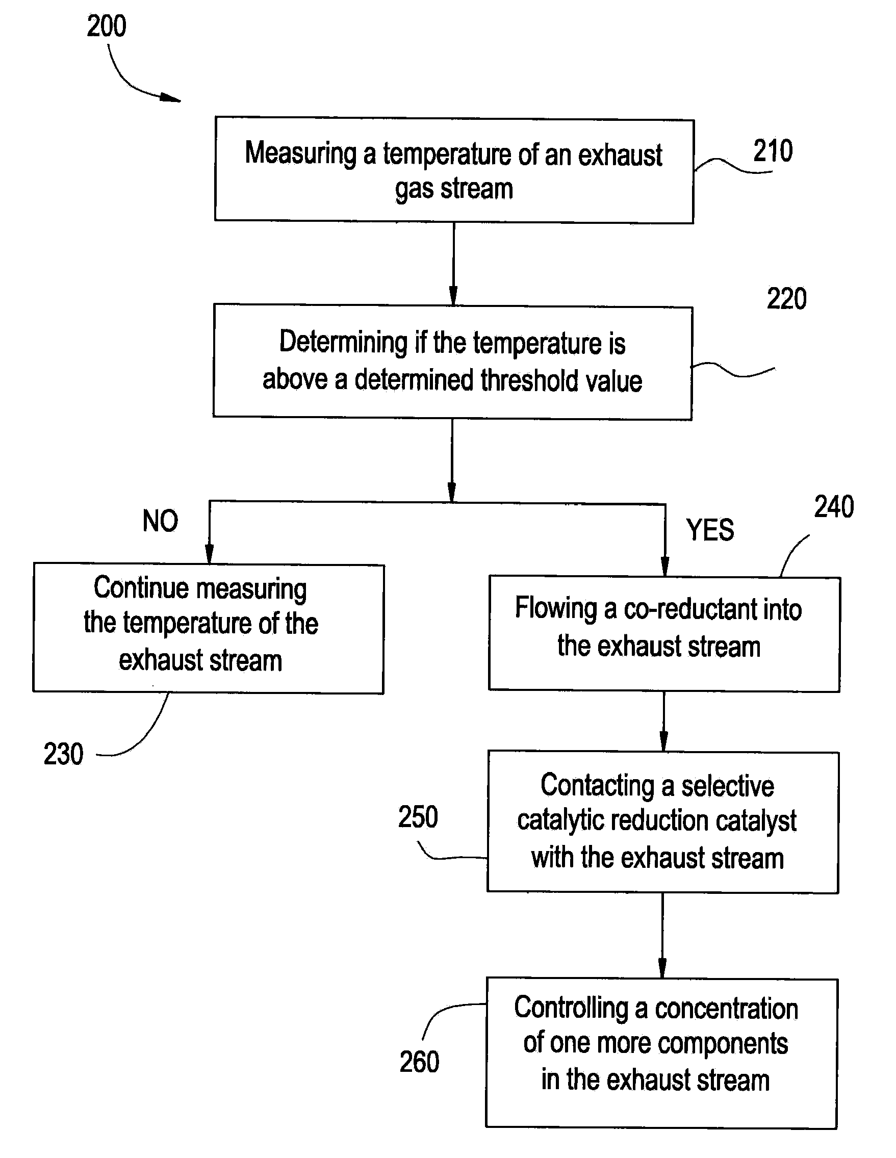
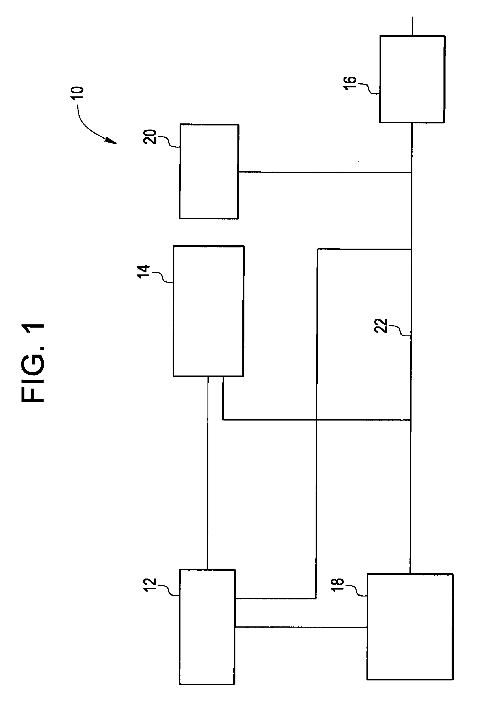
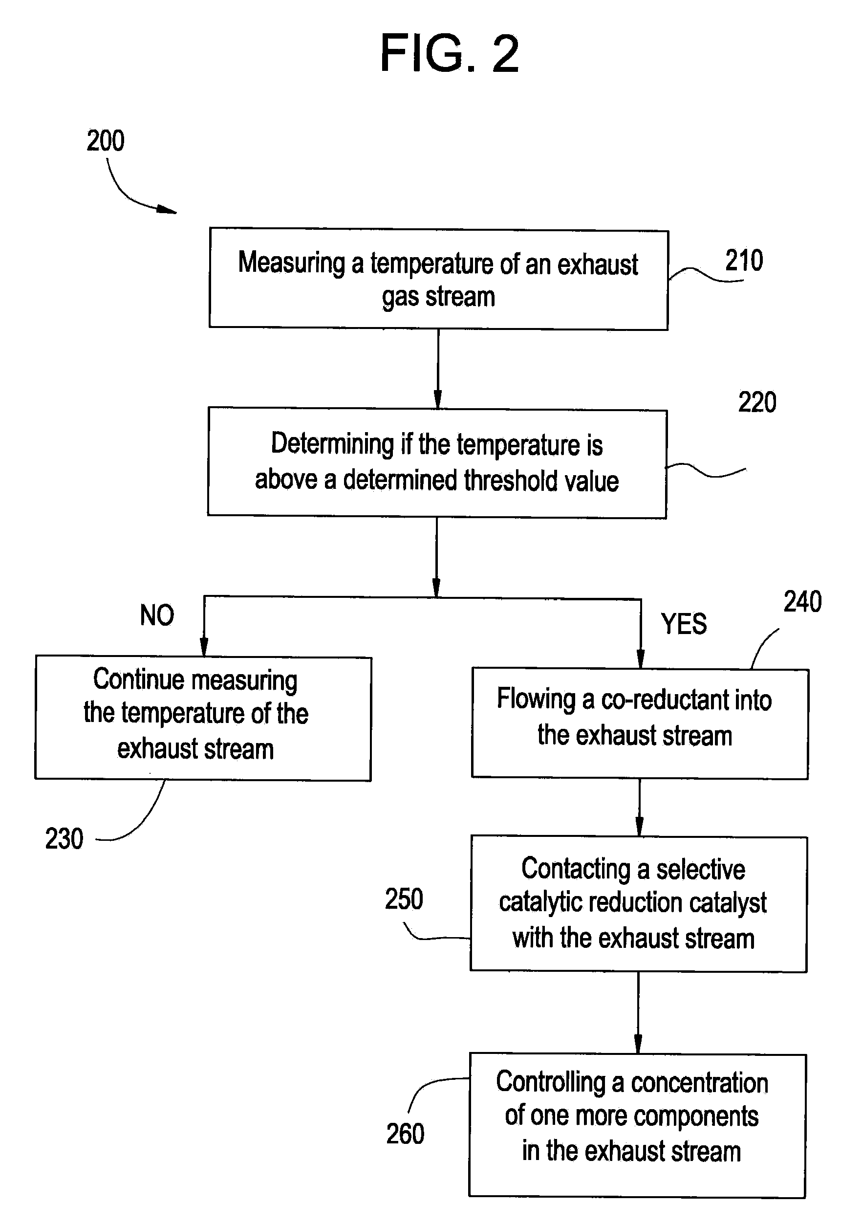
[0014]In one embodiment, the system may utilize a fuel source, as well as hydrogen gas (H2) obtained from a conversion reactor, to reduce emissions. The conversion reactor converts some of the fuel used by the engine (e.g., locomotive diesel fuel) into hydrogen. The fuel and / or hydrogen can be mixed with the exhaust stream and facilitate a reduction of NOx emissions in the presence of a hydrocarbon based selective catalytic reduction (SCR) catalyst bed. The fuel reductant, along, optionally, with the hydrogen-rich syngas co-reductant generated in-situ from the fuel (e.g., diesel) converter, will react with the NOx in the exhaust stream and reduce NOx to nitrogen at the surface of the SCR catalyst bed. The NOx concentration reduced in the exhaust gas stream.
[0017]Hydrogen gas can be derived from the primary fuel. The hydrogen-rich syngas can be used as a co-reductant with the fuel, particularly the partially oxidized main reductant derived from the secondary fuel, so that the HC-SCR bed can be used in the presence of exhaust gases without sacrificing the operable temperature range. For example, the system disclosed herein may be effective for NOx reductions at temperatures from about 150 degrees Celsius to about 600 degrees Celsius. Moreover, the use of hydrogen-rich syngas in the HC-SCR optimized bed permits lower levels of hydrocarbon to be used for efficient catalytic reduction of the nitrogen oxides

Problems solved by technology

Such emissions may be undesirable.

Method used


Image

  • Emission control system and method
  • Emission control system and method
  • Emission control system and method

Examples


Embodiment Construction

[0013]The present disclosure includes embodiments that relate to a system for controlling emissions. The disclosure includes embodiments that relate to a method for controlling emissions. A system or a method for controlling emissions may reduce the nitrogen oxides (NOx) emissions from the exhaust gas stream of a vehicle or a stationary source. Vehicles may include locomotives, marine vessels, off-highway vehicles, tractor-trailer rigs, and passenger vehicles. Emissions control refers to the ability to affect the compositional make up of an exhaust gas stream. As exhaust gas is a mixture of components, the reduction of one component almost invariably increases the presence of another component. For clarity of discussion, the chemical reduction of NOx is used as a non-limiting example of emission reduction insofar as the concentration of a determined species within the exhaust gas stream is controlled.

[0014]In one embodiment, the system may utilize a fuel source, as well as hydrogen ...


PUM

PropertyMeasurementUnit
Temperatureaaaaaaaaaa
Flow rateaaaaaaaaaa

Abstract

A system includes an exhaust conduit configured to conduct a stream of exhaust gas, wherein the exhaust conduit comprises a selective catalytic reduction catalyst reactor comprising a first catalyst composition; an fuel source configured to introduce a fuel into the exhaust gas stream within the exhaust conduit upstream of the selective catalytic reduction catalyst reactor; a catalytic partial oxidation reformer in fluid communication with the exhaust gas stream and upstream from the selective catalytic reduction catalyst reactor, wherein the catalytic partial oxidation reformer can introduce a hydrogen-rich syngas co-reductant into the exhaust gas stream, when a temperature of the exhaust fluid is less than a determined threshold temperature.

Description

BACKGROUND[0001]1. Technical Field[0002]The present disclosure includes embodiments that relate to a system for controlling emissions. The disclosure includes embodiments that relate to a method for controlling emissions.[0003]2. Discussion of Art[0004]Some vehicles may emit nitrogen oxides (NOx) during use. Such emissions may be undesirable.[0005]Emission controls have included engine modification and exhaust gas treatment. It may be desirable to have a system for emissions control that differs from those systems currently available. It may be desirable to have a method of controlling emissions that differs from those methods that are currently available.BRIEF DISCUSSION[0006]In one embodiment, a system for controlling emissions includes an exhaust conduit that conducts a stream of exhaust gas. The exhaust conduit includes a selective catalytic reduction catalyst including a first catalyst composition. A fuel can be introduced into the exhaust gas stream in the exhaust conduit upst...

Claims


Application Information

Patent Timeline
IPC IPC(8): F01N3/20
CPCB01D53/90Y02T10/24B01D2251/202B01D2251/204B01D2251/208B01D2258/012B01D2258/014F01N3/2066F01N3/208F01N2240/30F01N2370/02F01N2560/06F01N2610/03F01N2610/04F01N2610/05F01N2900/08B01D53/9409Y02T10/12
Inventor LIU, KEDELUGA, GREGG ANTHONYHANCU, DANNORTON, DANIEL GEORGEVITSE, FREDERICWINKLER, BENJAMIN HALE
Owner GENERAL ELECTRIC CO
Learn More