MEMS vacuum sensor based on the friction principle

a vacuum sensor and friction principle technology, applied in the field of sensor elements, can solve the problems of inability to evaluate the free oscillation, low oscillation quality of the oscillating mass element, etc., and achieve the widest possible measurement range, high resolution and precision

Inactive Publication Date: 2010-02-04
FRAUNHOFER GESELLSCHAFT ZUR FOERDERUNG DER ANGEWANDTEN FORSCHUNG EV +1
View PDF4 Cites 9 Cited by
  • Summary
  • Abstract
  • Description
  • Claims
  • Application Information

AI Technical Summary

Benefits of technology

[0013]The sensor element according to the present invention is suitable in particular for measuring pressures in the vacuum range and has a substrate and at least one mass element that is arranged spaced apart from the substrate and is connected elastically to the substrate and / or a support body that is fixed relative to the substrate. The gap resulting from the arrangement between the mass element and the substrate can be varied in terms of its width by oscillations of the mass element. At least one recess and / or at least one bushing is provided in the surface of the substrate delimiting the gap. The recess is suitable for reducing the damping of the oscillation of the mass element through the gas or plasma surrounding the mass element.
[0056]However, by using a glass substrate and silicon for the mass elements and suspension elements and for the support body and aluminum or gold for the substrate electrodes and feed lines, the sensor element can be operated at working temperatures of up to 350° C. The necessary evaluation and control electronic system is thereby completely replaced and can be embodied such that an electrically conductive connection between sensor element and electronic system of up to one meter in length does not cause any corruption of the measuring signal.

Problems solved by technology

This leads to the problem that the large surface of the mass element necessary for measurement at low pressures in connection with the small gap width required for higher pressures increases the damping so much that the oscillation quality of the oscillating mass element is so low, in particular at higher pressures, that an evaluation of the free oscillation is impossible.

Method used


Image

  • MEMS vacuum sensor based on the friction principle
  • MEMS vacuum sensor based on the friction principle
  • MEMS vacuum sensor based on the friction principle

Examples


Embodiment Construction

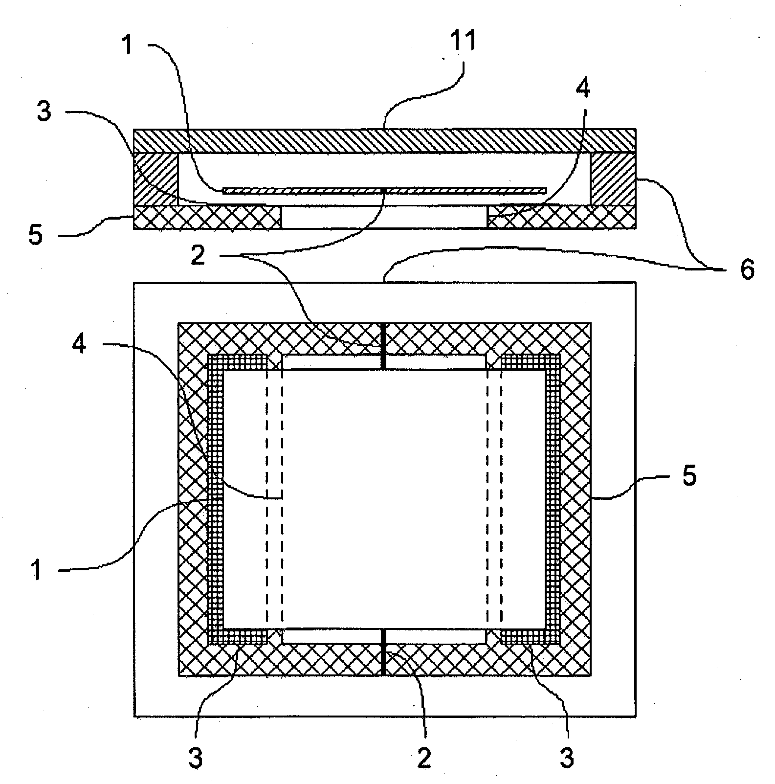
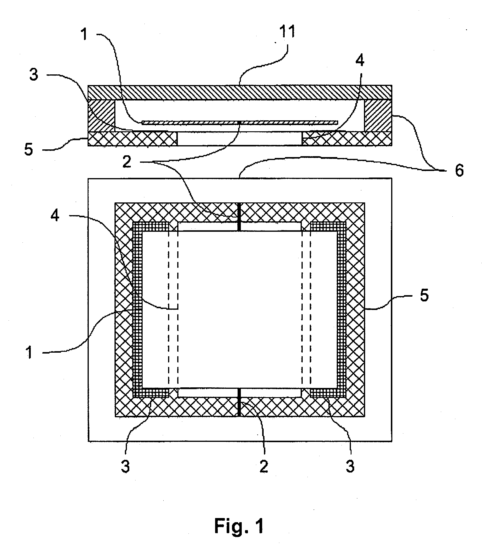
[0061]FIG. 1 shows a first mass element, e.g., detection mass 1, first suspension elements 2, substrate electrodes 3 for excitation and / or detection, bushing or recess 4 formed in substrate 5, a support body 6, and a cover 11. The sensor element according to the invention shown in FIG. 1 comprises a plate-like mass element 1, which is connected via two suspension elements 2 lying opposite one another to a support body 6, which is rigidly connected to a substrate 5. To reduce the damping at higher pressures, and in particular in the range of atmospheric air pressure, a bushing 4 is provided in the substrate 5 under the mass element 1. In order to minimize the influence of production-related geometric tolerances of the recesses or bushings 4 on the damping, the mass element 1 can be embodied in a perforated 7 manner, as shown in FIG. 2.

[0062]FIG. 3 shows, in addition to those features shown in FIG. 1, second suspension elements 9, and substrate electrodes 10, for control. Additionally...


PUM

PropertyMeasurementUnit
widthaaaaaaaaaa
widthaaaaaaaaaa
frequencyaaaaaaaaaa

Abstract

The invention relates to a sensor element for pressure measurement, having a substrate (5) and at least one mass element (1), which is arranged spaced apart from the substrate (5) and is connected in an oscillating manner to the substrate (5) and / or a support body (6) fixed relative to the substrate (5), so that a gap is formed between the mass element (1) and the substrate (5), the width of which can be varied through oscillations of the mass element (1). At least one recess and / or at least one bushing (4) is located in the surface of the substrate (5) delimiting the gap, which recess is used for reducing the damping of the oscillation of the mass element through the gas or plasma surrounding the mass element (1). The sensor element is used in particular in pressure sensors for measuring pressures in the vacuum range. Through the use of the sensor element according to the invention as a pressure sensor, maximum pressures up to the range of atmospheric air pressure can be recorded. The lowest pressures to be determined are in the range of 10−6 mbar.

Description

CROSS-REFERENCE TO RELATED APPLICATIONS[0001]The present application is a U.S. National Stage of International Patent Application No. PCT / EP2007 / 004078 filed Jan. 9, 2007, and claims priority of German Patent Application No. 10 2006 024 381.1 filed May 24, 2006. Moreover, the disclosure of International Patent Application No. PCT / EP2007 / 004078 is expressly incorporated by reference herein in its entirety.BACKGROUND OF THE INVENTION[0002]1. Field of the Invention[0003]The present invention relates to a sensor element, and in particular, to a sensor element with which particular pressures in the vacuum range can be measured.[0004]2. Discussion of Background Information[0005]The measurement of vacuum pressures plays a growing role in technology, particularly in high technology, where process control under vacuum has become very widespread. Examples where this type of process control is applicable include: material coating and material quenching and tempering, semiconductor technology, ...

Claims


Application Information

Patent Timeline
Patent Type & Authority Applications(United States)
IPC IPC(8): G01L21/22
CPCG01L21/22
Inventor KURTH, STEFFENTENHOLTE, DIRKHILLER, KARLAKAUFMANN, CHRISTIANGESSNER, THOMASDOETZEL, WOLFRAM
Owner FRAUNHOFER GESELLSCHAFT ZUR FOERDERUNG DER ANGEWANDTEN FORSCHUNG EV
Why Eureka
Try Eureka