Method and apparatus for fluid cleaning

a technology of fluid cleaning and method, applied in the direction of filtration separation, evaporator regulation/control, separation process, etc., can solve the problems of inability to clean fluid, disadvantages, and inability to operate in the prior art, so as to facilitate the state change of liquid contaminants, optimize the performance of the cleaning system, and save energy

Inactive Publication Date: 2010-02-04
OIL PURIFICATION SYST
View PDF20 Cites 20 Cited by
  • Summary
  • Abstract
  • Description
  • Claims
  • Application Information

AI Technical Summary

Benefits of technology

[0021]In another embodiment, the present invention includes an apparatus for cleaning a fluid that consists of a supply manifold, filtration assemblies, and an evaporation reservoir. The present invention provides several advantages over the prior art. For example, regardless of application size, in this embodiment a single line is used to supply pressurized fluid to the system. This line going to a supply manifold allows the fluid to be uniformly distributed to one or several filter assemblies the number of which are dictated by the size and operating characteristics of the application. Filtered oil from each of these assemblies is then directed to the evaporation reservoir and one of several heater assemblies designed to add sufficient energy to the fluid flow to facilitate the state change of liquid contaminants in the fluid. The collective volume of the heater assemblies accumulates at the bottom of the reservoir and is returned to the application via a single port at the bottom of the reservoir via gravity. An advantage of this configuration is that it too can be configured to optimize the performance of the cleaning system by dictating the number of heater assemblies that are used in the process. In addition, the reservoir includes an integral air flow system designed to evacuate any vapor created during the evaporation process. For example, this can be accomplished with the use of an electric fan that either pulls or pushes air through the chamber or can be accomplished pneumatically with an air pump moving air through the chamber. This provides a significant improvement over removal of the contaminates by the pressure differential created during evaporation.

Problems solved by technology

For various reasons, either the single vessel design or the two chamber design can be argued to have an advantage over the other, yet both suffer disadvantages regardless of configuration.
One problem is that the prior art typically operates with fixed ratios of filtration and evaporation with little or no means for adapting them to the particular contaminates generated by a given application.
As a result, these systems are poorly adapted to applications in which conditions change over time.
Another problem is that the prior art is typically poorly adapted to variations in size, resulting in mismatched operability between the fluid cleaning system and the application from which the fluid is to be cleaned.
Another problem is that the prior art relies on the pressure differential (created during the evaporation process) between the evaporation chamber and the ambient environment to vent contaminates from the evaporation chamber.
However, the prior art is not well suited for more demanding applications with more fluid contaminants.
Likewise, as the limit of absorption is approached, it will become increasingly difficult to remove contaminants to the air.
The prior art has failed to solve several problems inherent with fluid cleaning methods and systems, such as inefficiencies caused by poor matching of size and configuration between the fluid cleaning systems and the applications from which the fluids are being cleaned.
Another short coming of the prior art is a failure to provide for efficient air flow through the evaporative portion of the system to improve the removal of vapor generated during the cleaning of a fluid.

Method used


Image

  • Method and apparatus for fluid cleaning
  • Method and apparatus for fluid cleaning
  • Method and apparatus for fluid cleaning

Examples


Embodiment Construction

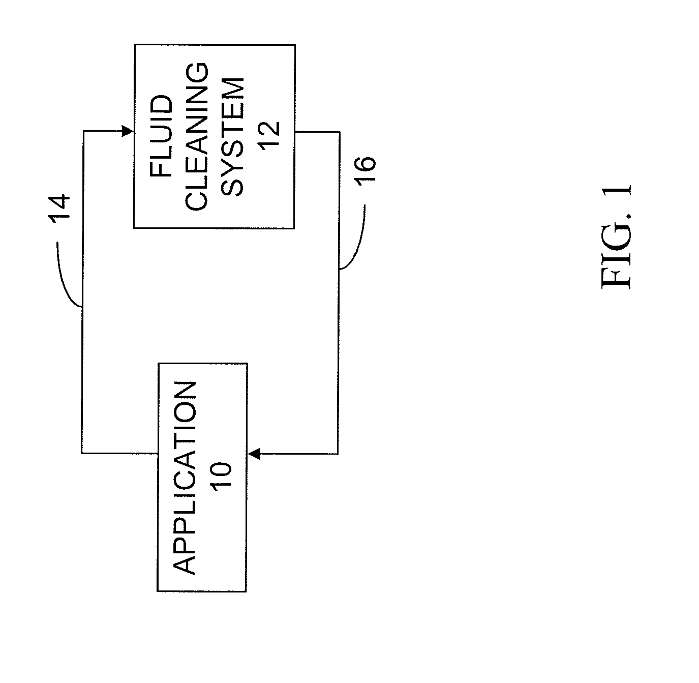
[0046]FIG. 1 is a schematic illustrating one example of the use of the present invention. In that embodiment, an application 10 is connected to a fluid cleaning system 12. Fluid from the application 10 is provided to the fluid cleaning system 12 via a supply line 14, where the fluid is cleaned as described in more detail hereinbelow. After cleaning, the fluid is returned to the application 10 via a return line 16.

[0047]The application 10 may be any mechanism or system utilizing a fluid which becomes contaminated. For example, the application 10 may be an internal combustion engine, a hydraulic system, a gearbox, or other applications. The fluid may be, for example, lubricating oil, hydraulic fluid, cooling fluid, or other fluids susceptible to contamination, such as solid particulate contamination and / or liquid contaminates. If left untreated, contaminants, both liquid and particulate, will usually reduce the usable life of the fluid and the application 10.

[0048]The fluid may be any...


PUM

PropertyMeasurementUnit
temperatureaaaaaaaaaa
humidityaaaaaaaaaa
poweraaaaaaaaaa

Abstract

A fluid cleaning system including a fluid supply port, a fluid return port, an evaporator including an air intake vent and an air exhaust vent, a ventilation system connected to the evaporator, and a fluid line. The evaporator includes a ventilation air path through the evaporator and connected to the intake vent and the exhaust vent in the evaporator. The evaporator also includes an active airflow device located along the ventilation path. The fluid line connects the evaporator between the fluid supply port and the fluid return port.

Description

CROSS-REFERENCE TO RELATED APPLICATIONS[0001]This application claims priority from U.S. provisional patent application Ser. No. 61 / 129,953, filed Aug. 1, 2008, which is incorporated by reference herein.STATEMENT REGARDING FEDERALLY SPONSORED RESEARCH AND DEVELOPMENT[0002]Not ApplicableFIELD OF THE INVENTION[0003]The present invention is generally related to fluid cleaning and more specifically, but not by way of limitation, to a system and method for fluid cleaning that is configurable based on the size of the application and the type of contamination created by the application.BACKGROUND OF THE INVENTION[0004]There are many methods and apparatuses that utilize fluids, such as fluids for lubricants in internal combustion engines, fluids to apply forces in hydraulic systems, fluids to regulate temperature such as in electrical transformers, and other uses of fluids. In general, it is important to keep those fluids clean and free from contaminants. However, the type and rate of contam...

Claims


Application Information

Patent Timeline
Patent Type & Authority Applications(United States)
IPC IPC(8): B01D1/00B01D35/18
CPCB01D1/0082B01D1/14C10M175/0058C10M175/0033B01D1/30
Inventor PRIEST, WILLIAM LAWRENCESLAWSON, GREGORY ALLEN
Owner OIL PURIFICATION SYST
Why Eureka
Try Eureka