Coil production method, coil of motor, and stator of motor

Inactive Publication Date: 2010-02-04
TOYOTA JIDOSHA KK
View PDF3 Cites 27 Cited by
  • Summary
  • Abstract
  • Description
  • Claims
  • Application Information

AI Technical Summary

Benefits of technology

[0020]The motor coil production method according to the invention having the above features can provide the following operations and effects.
[0021]Firstly, in the invention described in (1), in a coil production method for forming a coil of a motor in a spirally wound form by edgewise bending a rectangular conductor having a rectangular cross-section along a curved surface of a bending jig in a direction of a short side of the rectangular cross-section while one surface of the rectangular conductor is placed in contact with a bending jig, the method includes the deforming means for deforming the rectangular conductor uniformly over the entire width thereof so that the thickness corresponding to a length of the short side of the rectangular cross-section of the rectangular conductor is reduced to form a thickness changed portion corresponding to each of four corners of the coil constituted of the edgewise bent rectangular conductor. The deforming means forms the thickness changed portion of the rectangular conductor. The thickness changed portion of the rectangular conductor is edgewise bent to form the coil. Accordingly, the thickness changed portion is reduced in thickness over the entire width of the rectangular conductor instead of that only the inner peripheral side of the coil of the rectangular conductor is uniformly reduced in thickness before the edgewise bending as disclosed in Patent Literature 1. Thus, the material is uniformly spread forward and backward. The rectangular conductor therefore will not warp in a direction opposite to an edgewise bending direction, different from the case where only the inner peripheral side of the coil is decreased in thickness. This can produce the coil capable of ach

Problems solved by technology

However, in the conventional technique disclosed in Patent Literature 1, only the inner peripheral portion is squeezed, which conceivably causes a problem that interferes with edgewise bending.
This is therefore conceived as an interference with bending during edgewise bending and will cause winding disturbance in coil w

Method used


Image

  • Coil production method, coil of motor, and stator of motor
  • Coil production method, coil of motor, and stator of motor
  • Coil production method, coil of motor, and stator of motor

Examples


Example

First Embodiment

[0093]A detailed description of a first embodiment of the present invention will now be given referring to the accompanying drawings.

[0094]Firstly, the outline of a production process of a stator 50 in the first embodiment is briefly explained.

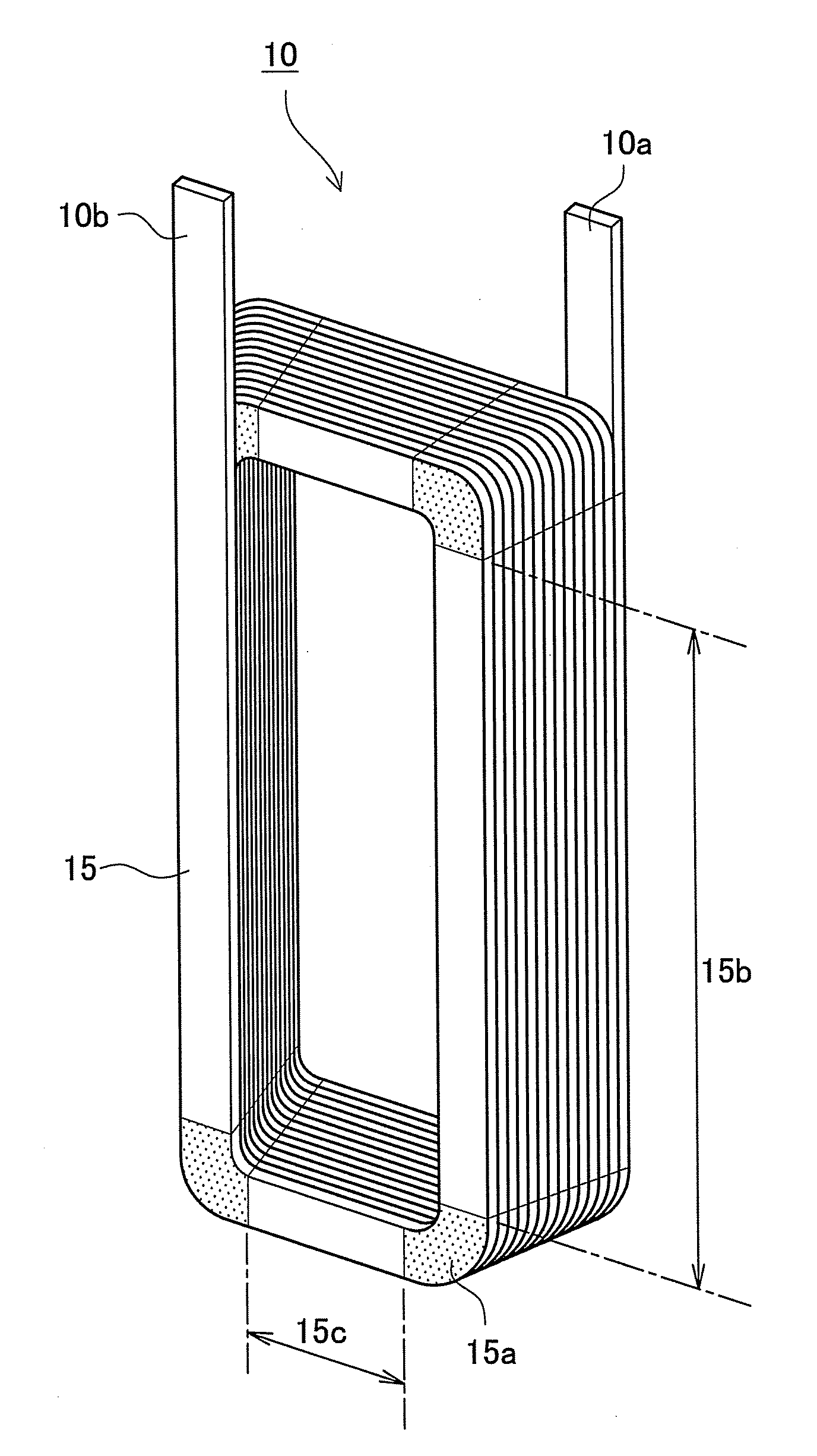
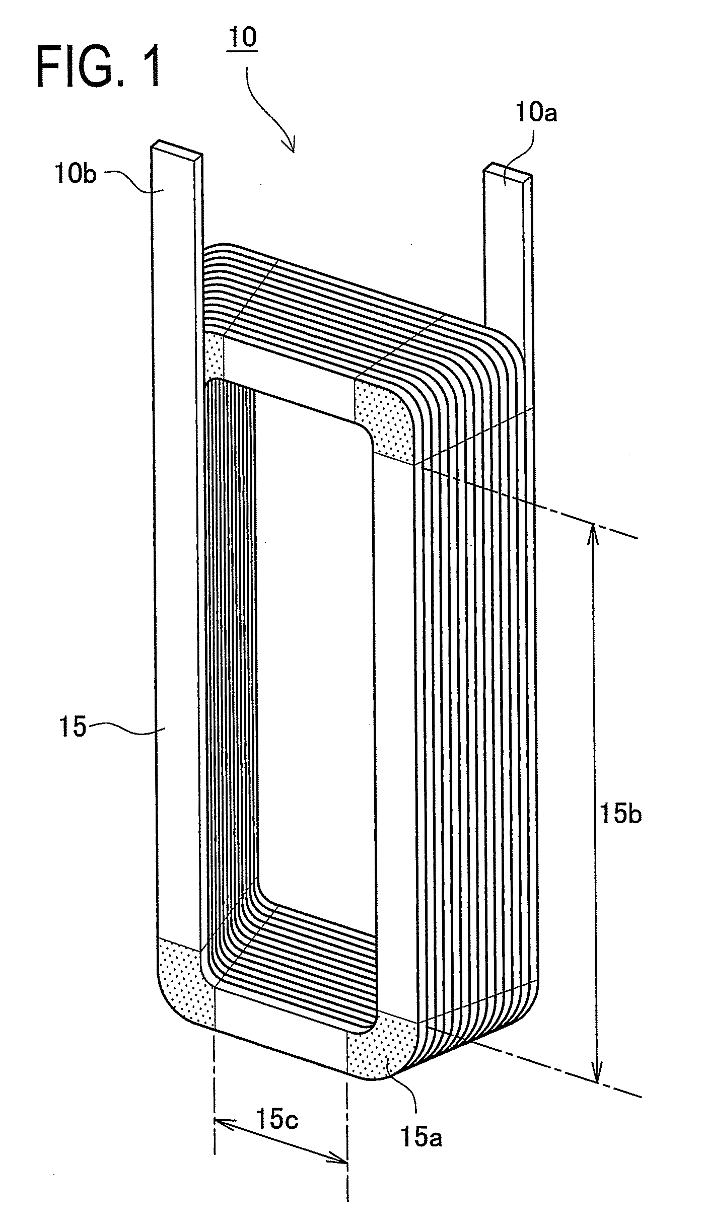
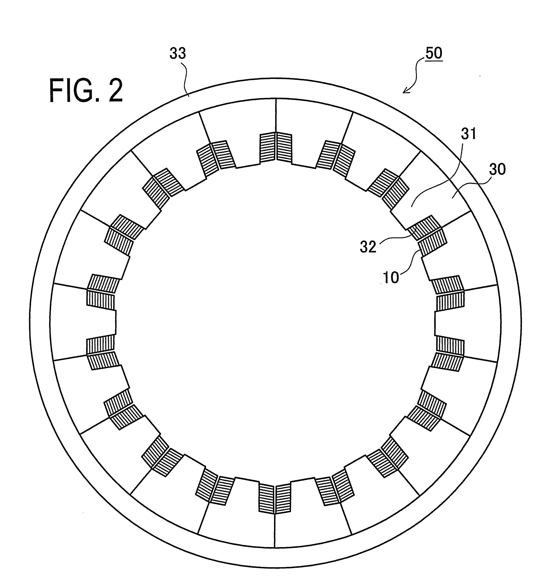
[0095]FIG. 1 is a perspective view of a coil 10 in a wound state in the first embodiment. FIG. 2 is a cross-sectional view of a stator core 30 with the coil 10 inserted therein. FIG. 3 shows a stator 50 whose coil ends are molded by resin.

[0096]The coil 10 is formed of a rectangular cross-section conductor (“rectangular conductor”) 15 that is spirally wound as shown in FIG. 1 to conform to the outer shape of a tooth 31 provided in the stator core 30. Thus, long sides 15b and short sides 15c are formed so that the short sides 15c are gradually longer from the inner periphery side to the outer periphery side of the stator core 30. The rectangular conductor 15 is made of a good conductive metal, such as copper, formed in a strip s...

Example

Second Embodiment

[0160]Next, a second embodiment will be described below.

[0161]The second embodiment is substantially the same as the first embodiment excepting the configuration of the deforming mechanism 62. Thus, the deforming mechanism 62 is explained below.

[0162]FIGS. 15A and 15B show the deforming mechanism 62 in the second embodiment; FIG. 15A shows that during rolling and FIG. 15B shows that during wire feeding.

[0163]Deforming rollers 73 are placed above and below the rectangular conductor 15 to form a thickness changed portion 15a in the rectangular conductor 15. As shown in FIG. 15A, during rolling, the deforming rollers 73 are rotated while pressing the rectangular conductor 15 from above and below.

[0164]After the thickness changed portion 15a is formed by the deforming rollers 73, as shown in FIG. 15B, the rollers 73 are retracted to allow the rectangular conductor 15 to be fed by a predetermined distance. The feeding mechanism can feed the rectangular conductor 15 to an...

Example

Third Embodiment

[0168]Next, a third embodiment will be described below.

[0169]The third embodiment is substantially the same as the first embodiment excepting the configuration of the deforming mechanism 62. Thus, the deforming mechanism 62 is explained below.

[0170]FIGS. 16A and 16B show the deforming mechanism 62 of the third embodiment; FIG. 16A shows that during press and FIG. 16B shows that during wire feeding.

[0171]Presses 75 are placed above and below the rectangular conductor 15 to form a thickness changed portion 15a in the rectangular conductor 15. As shown in FIG. 16A, during rolling, the presses 75 press the rectangular conductor 15 from above and below to form each thickness changed portion 15a.

[0172]After the thickness changed portion 15a is formed by the presses 75, as shown in FIG. 16B, the presses 75 are retracted to allow the rectangular conductor 15 to be fed by a predetermined distance. The feeding mechanism can feed the rectangular conductor 15 to an arbitral pos...


PUM

PropertyMeasurementUnit
Lengthaaaaaaaaaa
Thicknessaaaaaaaaaa

Abstract

A coil production method capable of improving the space factor of a rectangular conductor with respect to the slot of a stator core, a coil of a motor, and a stator of a motor. The coil production method in which one surface of a rectangular conductor is brought into contact with a shaft with guide, and edgewise bending is performed along the curved surface of the shaft, wherein a deforming mechanism for reducing the plate thickness of a plate thickness changed portion corresponding to each of four corners of a coil over the entire width of the rectangular conductor is provided, the deformation mechanism is used to deform the plate thickness changing portion, and the plate thickness changing portion of the rectangular conductor is edgewise-bent to form a coil.

Description

CROSS-REFERENCE TO RELATED APPLICATIONS[0001]This is a national phase application filed under 35 U.S.C 371 of PCT / JP2008 / 050475 filed on Jan. 9, 2008, which claims the benefit of priority from the prior Japanese Patent Application No. 2007-008376 filed on Jan. 17, 2007, the entire contents of all of which are incorporated herein by reference.FIELD OF THE INVENTION[0002]The present invention relates to a stator of motor using a coil produced by edgewise bending a rectangular conductor into a spirally wound form, a coil of motor, and a coil production method.BACKGROUND OF THE INVENTION[0003]A stator to be used in a motor is generally a wire-wound stator. In recent years, however, downsized and high-power motors have been demanded. Thus, there is proposed a method of producing a coil by edgewise bending a rectangular conductor to be used in the stator.[0004]The stator using the coil produced by edgewise bending the rectangular conductor is unsuitable for lap-winding but has a better he...

Claims


Application Information

Patent Timeline
IPC IPC(8): H02K3/04H02K15/085
CPCH01F27/2847H01F41/065Y10T29/49009H02K3/18H02K15/045H01F41/0691H01F41/071H01F41/077
Inventor FUBUKI, SHINGOHARADA, KENJI
Owner TOYOTA JIDOSHA KK
Why Eureka
Try Eureka