Power Supplying Apparatus

a power supply and power mosfet technology, applied in the direction of electric variable regulation, process and machine control, instruments, etc., can solve the problems of large switching losses and control power, under-mentioned drawbacks of high control power, and large switching losses of upper/lower-sided power mosfets, so as to reduce the control power of the upper/lower-sided power mosfets and minimize the switching loss. , the effect of improving efficiency

Inactive Publication Date: 2010-02-04
HITACHI LTD
View PDF7 Cites 33 Cited by
  • Summary
  • Abstract
  • Description
  • Claims
  • Application Information

AI Technical Summary

Benefits of technology

[0012]In accordance with the present invention, when the power supply apparatus is driven under the light load condition, the output voltage thereof can be recovered by turning ON the upper-sided power MOSFET only 1 time. As a result, the switching losses of the upper-sided / lower-sided power MOSFETs can be minimized, and furthermore, since the PWM oscillator and other circuits provided in the control unit are turned OFF (stopped), the control power thereof can be decreased in the largest degree.
[0013]Also, since the fast response of the power supply apparatus is not deteriorated which is applied to the power reduction under the light load operation, there is such a merit of achieving compatibility, namely, an efficiency can be improved due to power saving effects achieved when the power supply apparatus is driven under the light load condition, and furthermore, the fast response can be secured.
[0014]In addition, in accordance with the technical idea of the present invention, since this technical idea is applied to a digital control operation in a digital power supply apparatus, the following merits may be obtained: That is, a setting value may be easily tuned to such a point at which the highest power saving level may be expected during a light load driving condition, so that a higher power saving effect by the digital control operation may be expected, as compared with that of the analog control operation.

Problems solved by technology

As a result, although control power of the power supply apparatus is low, there is such a drawback that switching losses of the upper-sided / lower-sided power MOSFETs become large.
As a result, although switching losses may be caused by turning ON / OFF both the upper-sided / lower-sided power MOSFETs only one time, the below-mentioned drawback of high control power may occur.
As a result, there is such a drawback that both switching losses and control power become large.

Method used


Image

  • Power Supplying Apparatus
  • Power Supplying Apparatus
  • Power Supplying Apparatus

Examples


embodiment 1

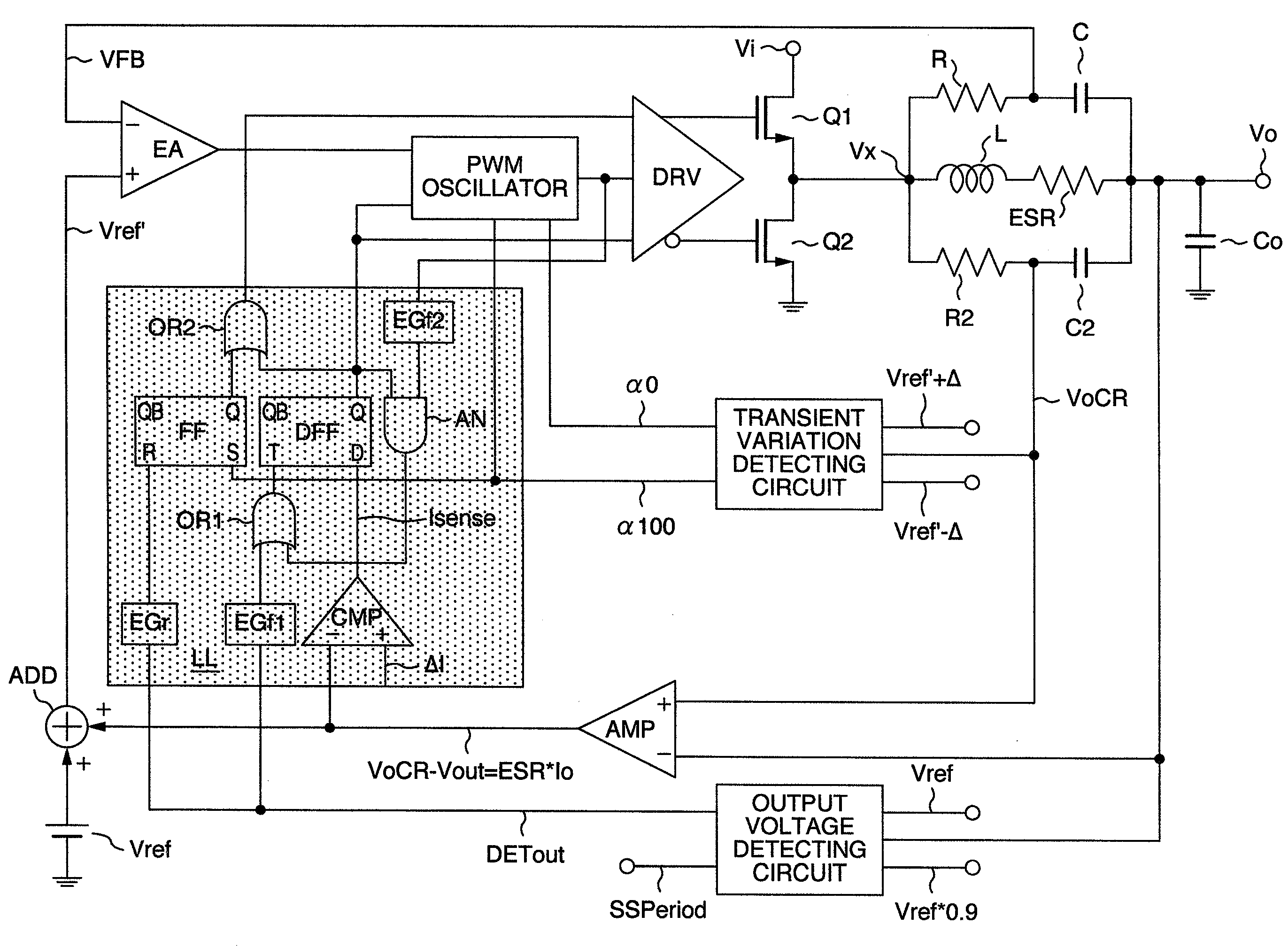
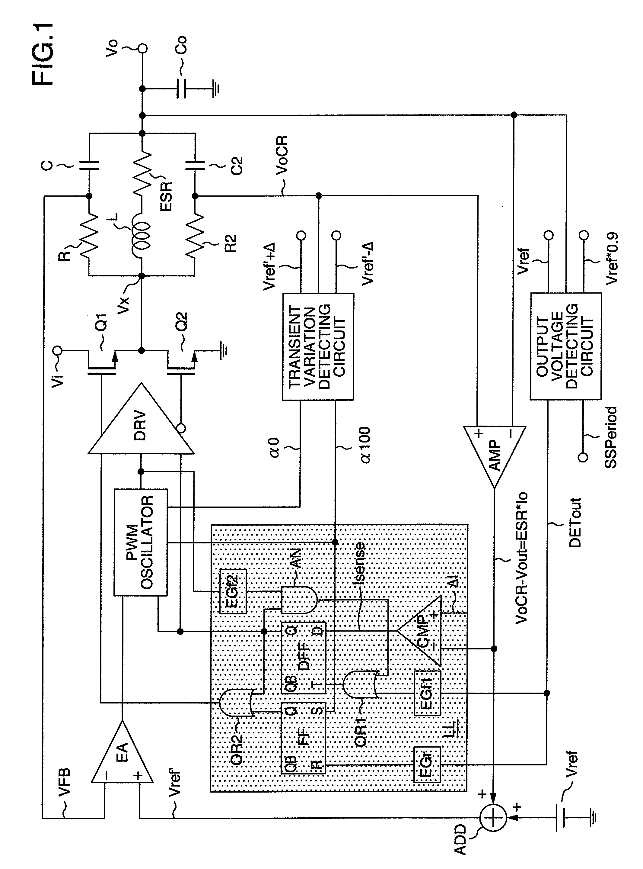
[0033]A circuit diagram of a power supply apparatus according to an embodiment 1 of the present invention is indicated in FIG. 1. In FIG. 1, symbol “Vi” shows an input terminal, and symbol “Vo” indicates an output terminal. An upper-sided power MOSFET (Q1) is connected to the input terminal “Vi”, and a lower-sided power MOSFET (Q2) is connected to the ground side. An LC smoothing filter is connected to a midpoint between the power MOSFETs (Q1) and (Q2), while the LC smoothing filter corresponds to a power series output filter constructed by employing an inductor “L” and a capacitor “Co.” Then, a first CR smoothing filter arranged by a resistor “R” and a capacitor “C” and a second CR smoothing filter arranged by a resistor “R2” and a capacitor “C2” are connected in a parallel manner between both terminals of the inductor “L” of the LC smoothing filter. In addition, the output terminal Vo, one input “(−)” of a differential amplifier “AMP” and an input of an output voltage detecting ci...

embodiment 2

[0061]FIG. 8 is a circuit block diagram of a power supply apparatus according to an embodiment 2 of the present invention. It should be noted that the same reference numerals shown in FIG. 1 will be employed as those for denoting the same, or similar structural elements represented in FIG. 8. The power supply apparatus shown in FIG. 8 has the below-mentioned different points from those of FIG. 1: That is, as the stopping (turn-OFF) signal for turning OFF both the lower-sided power MOSFET (Q2) and the PWM oscillator “PWM”, the output “Q” of the D type flip-flop DFF is not employed, but the output of the OR gate OR2 is employed which is similarly used to the upper-sided power MOSFET (Q1). In this case, when the power supply apparatus is driven under light load condition, the upper-sided power MOSFET (Q1) is turned ON one time so as to recover the output voltage to the predetermined voltage, which is similar to that of FIG. 1. However, in accordance with the embodiment 2, since the low...

embodiment 3

[0066]FIG. 9 shows an embodiment 3 of the present invention in which the power supply apparatus indicated in FIG. 1 is controlled in a digital manner. In FIG. 9, in order to replace circuits and functions of FIG. 1 by digitally-operable circuits and functions, the below-mentioned seven, or more technical ideas are conducted: That is,

[0067]1) the converted voltage “VFB” which has been fed back from the output of the first CR smoothing filter constituted by the capacitor C and the resistor R is obtained from the output terminal “Vo.”

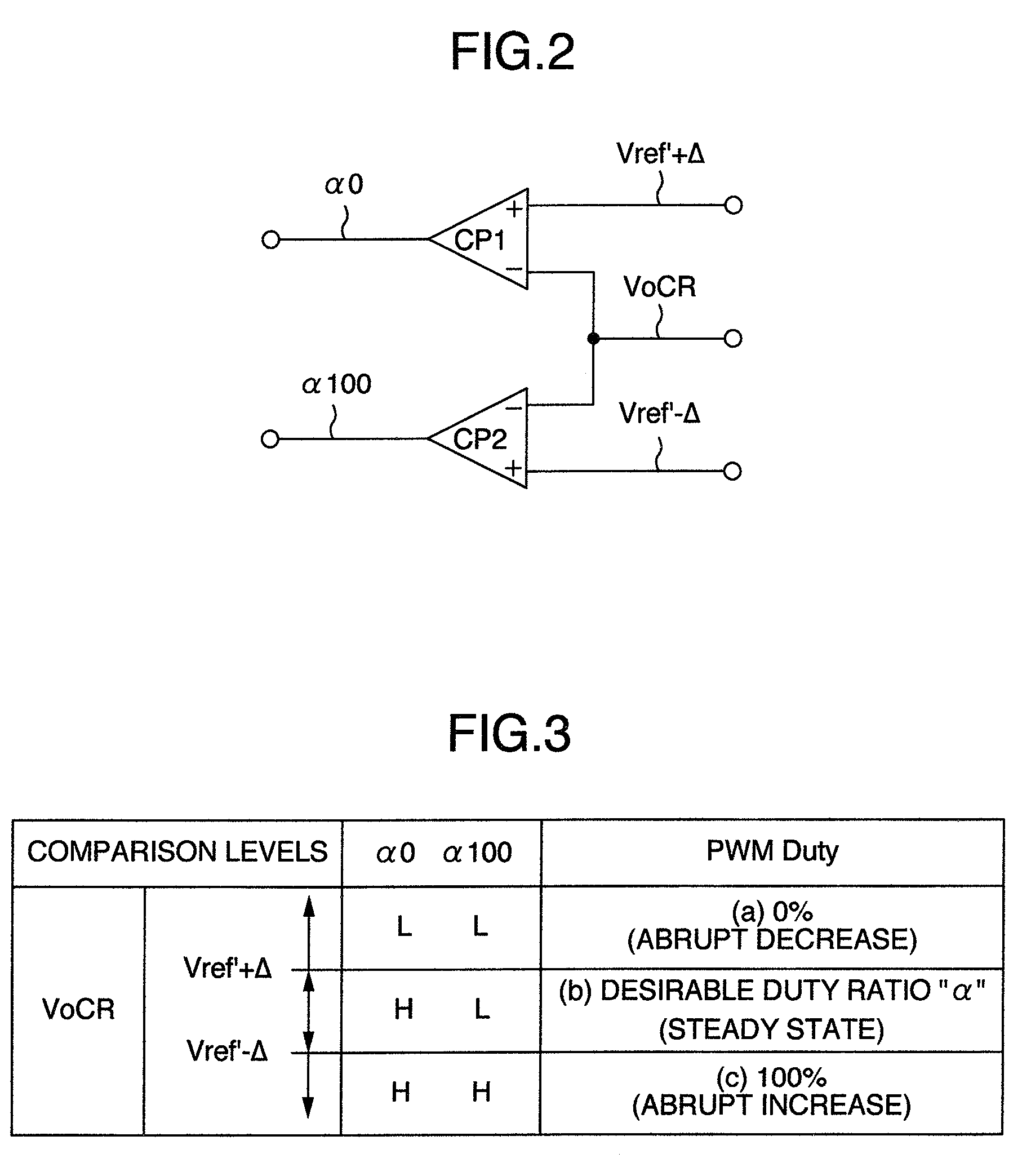
[0068]2) the transient variation detecting circuit TVD arranged by the comparators CP1 and CP2 is separately provided with respect to a digital signal processing unit 100 for performing a high-speed processing.

[0069]3) the new reference voltage “Vref′” generated by operating the differential amplifier AMP and the adder ADD is replaced by such a new digital reference voltage signal “Dref′” which is generated in such a manner that in the digital processing u...


PUM


Abstract

A first-order feedback control power supply apparatus being arranged in such a manner that when the apparatus is driven under light load condition, a current flowing through an inductor is detected by employing a second CR smoothing filter; when the present load condition is judged as a light load condition based upon the detected inductor current, both upper-sided/lower-sided power MOSFETs and a PWM oscillator are turned OFF so as to be brought into sleep states; when an output voltage of the power supply apparatus is lowered and the lowered output voltage reaches a lower limit threshold of a transient variation detecting circuit, the upper-sided power MOSFET is turned ON to recover the output voltage; and when the output voltage of the power supply voltage reaches a predetermined voltage, the upper-sided power MOSFET is turned OFF so as to be again brought into the sleep state.

Description

BACKGROUND OF THE INVENTION[0001]1. Field of the Invention[0002]The present invention generally relates to a power supply apparatus. More specifically, the present invention is directed to an improvement in efficiencies when a first-order feedback control power supply (virtual title) is driven under light load condition, and moreover, is directed to control technology capable of realizing compatibility between light load driving of the first-order feedback control power supply apparatus and a fast response thereof which constitutes the feature of the first-order feedback control power supply apparatus.[0003]2. Description of the Related Art[0004]As to improvements in efficiencies when power supply apparatuses are driven under light load conditions, various sorts of examples have been proposed in which these power supply apparatuses are driven in a burst mode, a voltage mode, a ripple mode, and other modes. In an example as to the above-described burst mode, a current flowing through...

Claims


Application Information

Patent Timeline
Patent Type & Authority Applications(United States)
IPC IPC(8): G05F1/565
CPCH02M3/156Y02B70/16H02M2001/0032H02M1/0032Y02B70/10
Inventor SASE, TAKASHIKANOUDA, AKIHIKOTSUYUKI, YOSUKE
Owner HITACHI LTD
Why Eureka
Try Eureka