Replaceable Electrostatic Chuck Sidewall Shield

a sidewall shield and electrostatic chuck technology, applied in the direction of basic electric elements, electrical equipment, semiconductor/solid-state device manufacturing, etc., can solve the problems of contaminating the plasma chamber and the wafer currently being processed, esc to deteriorate, and esc sidewall ablation, so as to improve performance, fast and efficient replacement, and more resistant to damage

Active Publication Date: 2010-02-04
TAIWAN SEMICON MFG CO LTD
View PDF22 Cites 37 Cited by
  • Summary
  • Abstract
  • Description
  • Claims
  • Application Information

AI Technical Summary

Benefits of technology

[0012]An advantage of embodiments of the present invention is that the replaceable sidewall shield is more resistant to damage arising from the conditions within a plasma chamber than prior art methods utilizing epoxy. Additionally, in situations where epoxy is initially applied, the replaceable sidewall shield prevents the epoxy from coming into contact with the plasma gas, and the by-products of the plasma process within the chamber. This results in improved performance and longer life for the electrostatic chuck.
[0013]A further advantage of embodiments of the present invention is that a replaceable sidewall shield can be quickly and efficiently replaced, thus allowing for cost-effective rehabilitation of an electrostatic chuck that is otherwise near the limit of its useful life.

Problems solved by technology

The plasma and plasma by-products may cause the ESC to deteriorate in a process known as plasma etching or process gas erosion.
Another factor that may contribute to the deterioration of ESCs is the installation and removal of process kits.
Some process kits surrounding the ESC in the chamber may abrade the ESC sidewall when the kits are installed and removed.
The introduction of these particles into the plasma chamber contaminates the plasma chamber and the wafer presently being processed.
Ultimately, the problems of gas leakage and edge arcing shorten the useful life of the ESC.
Applying epoxy to these areas slows down ESC deterioration, but the epoxy is not resistant to parts abrasion caused by the plasma or plasma by-products, and as a result, gas leakage and edge arcing may continue to occur.
In addition, application of epoxy to the ESC is permanent, making it difficult to refurbish the ESC as the epoxy or other elements of the ESC deteriorate.

Method used


Image

  • Replaceable Electrostatic Chuck Sidewall Shield
  • Replaceable Electrostatic Chuck Sidewall Shield
  • Replaceable Electrostatic Chuck Sidewall Shield

Examples


Embodiment Construction

[0019]The making and using of embodiments of the present invention are discussed in detail below. It should be appreciated, however, that the present invention provides many applicable inventive concepts that can be embodied in a wide variety of specific contexts. The specific embodiments discussed are merely illustrative of specific ways to make and use the invention, and do not limit the scope of the invention.

[0020]The present invention will be described with respect to embodiments in a specific context, namely an electrostatic chuck (ESC) employed in a plasma chamber. The invention may also be applied, however, to other types of chucks and to other types of processing.

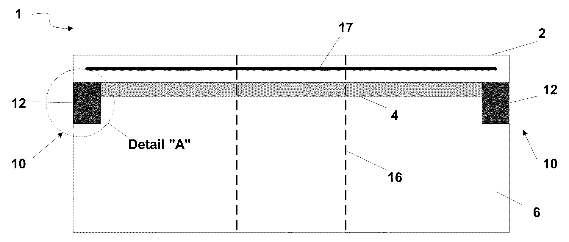
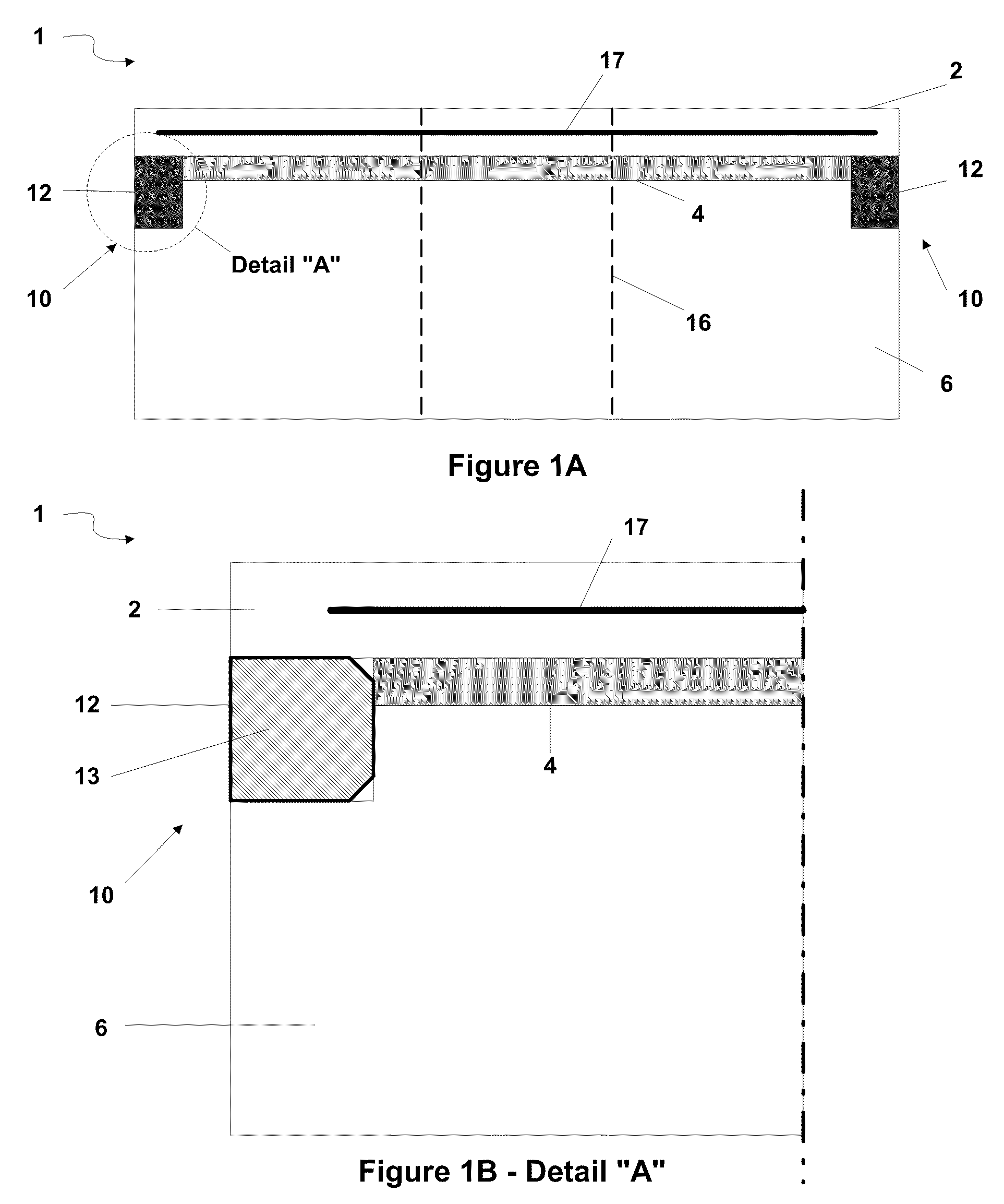
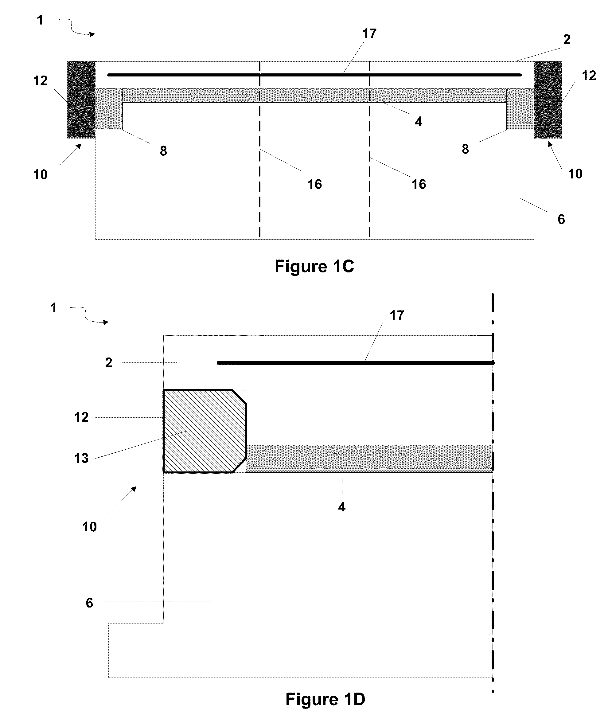
[0021]Referring now to the drawings, FIGS. 1A-1D illustrate a cross-sectional area of an ESC 1. In the illustrated embodiment shown in FIG. 1A, ESC 1 comprises a top member 2, a bonding layer 4, a base member 6, an indentation 10, a replaceable sidewall shield 12, a gas hole 16, and a conductive pole 17.

[0022]Condu...


PUM


Abstract

A replaceable electrostatic chuck sidewall shield is provided. The replaceable electrostatic chuck sidewall shield fills or partially fills an indentation located between a base member and a top member of an electrostatic chuck, such that the replaceable electrostatic chuck sidewall shield may protect an epoxy in the indentation or may replace the epoxy within the indentation. The replaceable electrostatic chuck sidewall shield may be fully contained with the indentation. The replaceable electrostatic chuck sidewall shield may also cover an epoxy in the indentation such that the replaceable electrostatic chuck sidewall shield protrudes beyond the indentation. In an alternate embodiment, the replaceable electrostatic chuck sidewall shield substantially covers the area in which a conductive pole is embedded in a bipolar electrostatic chuck.

Description

[0001]This application claims the benefit of U.S. Provisional Application No. 61 / 084,865, filed on Jul. 30, 2008, entitled “Replaceable Electrostatic Chuck Side-Wall Shield,” which application is hereby incorporated herein by reference.TECHNICAL FIELD[0002]The present invention relates generally to an apparatus for processing integrated circuits and, more particularly, to an apparatus for sealing the sidewall of an electrostatic chuck.BACKGROUND[0003]In modern integrated circuit semiconductor manufacturing, etching is a process used to pattern circuits on a semiconductor. Plasma etching is one type of etching process, in which a high-speed stream of ions is directed at a wafer. The ions etch the surface of the wafer, thus modifying the wafer's physical topography and allowing the creation of a pattern. Plasma etching apparatuses typically include a plasma chamber and an electrostatic chuck (ESC) residing within the plasma chamber.[0004]The ESC is a device that employs electricity to...

Claims


Application Information

Patent Timeline
Patent Type & Authority Applications(United States)
IPC IPC(8): H01L21/683
CPCH01L21/6833
Inventor LIU, HSI-SHUIWANG, YEH-CHIEHPAI, JIUN-RONG
Owner TAIWAN SEMICON MFG CO LTD
Why Eureka
Try Eureka