Turbine Rotor

a turbine rotor and rotor body technology, applied in the field of turbine rotors, can solve the problems of difficult to meet the requirements of both properties of only one material, inability to apply oxidation, excessive oxidation of penetration beads, etc., and achieve the effect of improving the reliability of welds

Inactive Publication Date: 2010-02-04
HITACHI LTD
View PDF7 Cites 18 Cited by
  • Summary
  • Abstract
  • Description
  • Claims
  • Application Information

AI Technical Summary

Benefits of technology

[0011]The present invention eliminates the necessity of inspecting the flaws and shape of the penetration beads, improving the reliability of the weld.

Problems solved by technology

However, it is difficult for only one material to satisfy both properties for high pressure and low pressure.
Since the inside of the rotor center hole is air atmosphere which cannot be substituted by inert atmosphere, back shield for preventing oxidation cannot be applied.
When welding is performed by introducing a welding torch from an outer peripheral side, the weld metal reacts with air in the center hole, so that the penetration beads are excessively oxidized.
The shape of the penetration beads excessively oxidized becomes irregular, which may largely differ from that indicated by a design drawing, causing flaws in some cases.
When not inspecting the shape of such penetration beads formed at the center hole of the rotor, the turbine rotor does not become a desired one from the viewpoint of the reliability of strength.
A rotor provided with the through hole as described above may receive concentrated stress during the rotation, which is undesirable from the viewpoint of the strength maintenance and the reliability of the rotor.

Method used


Image

  • Turbine Rotor
  • Turbine Rotor
  • Turbine Rotor

Examples


example 1

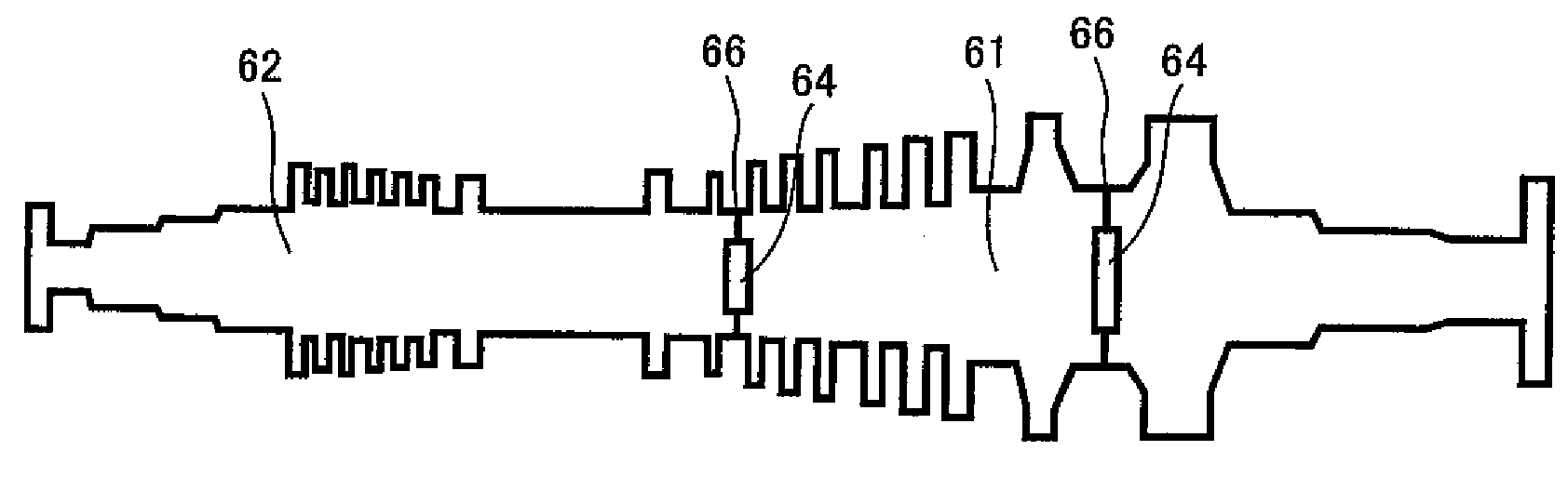
[0047]Example 1 of the present invention will be described below using FIGS. 1 to 11. FIG. 1 is a sectional view of the turbine rotor for high and low pressure steams according to the present invention. The turbine rotor for high and low pressure steam shown in FIG. 1 is divided into two components, that is, a rotor 62 for high pressure and a rotor 61 for low pressure, which are connected to each other by a weld 6 (weld metal 66) to construct the turbine rotor. A joint connected by the weld 6 has a hollow portion 64, which decreases the weight of the turbine rotor. The rotor 62 for high pressure includes 1% Cr—Mo—V steel. The rotor 61 for low pressure includes 3 to 4% Ni—Cr—Mo—V steel. Table 1 shows chemical compositions (weight percent) of weld wires and materials constituting the rotor of a typical turbine rotor, the rest of the compositions being Fe.

TABLE 1Steel gradeCSiMnNiCrMoNbVMaterial for high0.290.040.770.521.131.353—0.27pressure 1: 1%Cr—Mo—V steelWeld(1) 1.25%0.060.500.99—...

example 2

[0069]With reference to FIG. 14, example 2 of the present invention will be described. This example is the same as Example 1 except for the length of the outer contact face 32 in the axial direction, and therefore a description of the same other components as Example 1 will be omitted below.

[0070]The result of a preliminary verification test performed prior to this example will be described below. The length L2 of the outer contact face 32 in the axial direction was 2.5 mm before and after the welding. That is, the penetration tip of the weld metal 6 did not reach the outer contact face 32 in the axial direction. In this case, the effect was not obtained of preventing the spouting of the metal by compression of the outer contact face 32 in the axial direction as described in FIG. 11. This result shows that in order to obtain the effect of preventing the spouting of the weld metal 6, the penetration tip of the weld metal 6 needs to be located on the outer contact face 32 in the axial...

example 3

[0071]With reference to FIG. 15, example 3 of the present invention will be described. This example is the same as Example 1 except for the length of the outer contact face 32 in the axial direction, and therefore a description of the same other components as Example 1 will be omitted below.

[0072]The result of a preliminary verification test performed prior to this example will be described below. The length L2 of the outer contact face 32 in the axial direction was 2.5 mm before the welding and 0 mm after the welding. That is, the weld metal 6 included the entire area of the outer contact face 32 in the axial direction. In this case, since the outer contact face 32 in the axial direction disappeared, the effect of preventing the spouting of the weld metal was not obtained. This result shows that in order to obtain the effect of preventing the spouting of the metal, it is essential to leave a part of the outer contact face 32 in the axial direction. The section of the vicinity of th...


PUM

PropertyMeasurementUnit
lengthaaaaaaaaaa
steam temperatureaaaaaaaaaa

Abstract

An object of the present invention is to provide a turbine rotor with high reliability of strength. The turbine rotor includes two rotors which are connected at the butted portions of the rotors via a weld without forming penetration beads. Specifically, the turbine rotor includes a rotor for low pressure, a rotor for high pressure, and a center hole formed at a center portion of the turbine rotor. The rotors for low pressure and for high pressure are integrated together into a steam turbine rotor by welding respective ends of the rotors to each other. The respective ends of the rotors are in contact with each other via at least two contact faces in a radial direction and an axial direction of the turbine rotor. At least parts of the respective ends are welded together.

Description

CLAIM OF PRIORITY[0001]The present application claims priority from Japanese Patent Application JP 2008-197171 filed on Jul. 31, 2008, the content of which is hereby incorporated by reference into this application.FIELD OF THE INVENTION[0002]The present invention relates to turbine rotors.BACKGROUND OF THE INVENTION[0003]With the growing concern about environmental problems, steam turbine power plants have been required to have higher efficiency and higher output capacity by increasing the temperature and pressure of steam. Properties required for material of a steam turbine rotor are appropriate high-temperature creep rupture strength at high pressure (high temperature), and appropriate tensile strength and toughness at low pressure (low temperature). However, it is difficult for only one material to satisfy both properties for high pressure and low pressure. Thus, the following method has been known. The steam turbine rotor is divided into a plurality of stages, each of which is m...

Claims


Application Information

Patent Timeline
Patent Type & Authority Applications(United States)
IPC IPC(8): F01D5/14
CPCB23K31/02F05D2230/232F01D5/063B23K33/004
Inventor NISHIOKA, EIJIARAI, MASAHIKOHIRUTA, RYUSUKEDOI, HIROYUKI
Owner HITACHI LTD
Why Eureka
Try Eureka