
Conductive multilayer stack

a multi-layer, conductive technology, applied in the direction of synthetic resin layered products, chemistry apparatus and processes, transportation and packaging, etc., can solve the problems of not meeting the requirements of stealth jet fighters, the service life is limited, and the majority of polymeric materials are not infrared-reflective, so as to improve the service life, and reduce the effect of ir reflection

Inactive Publication Date: 2010-02-04
PPG IND INC
View PDF29 Cites 49 Cited by
  • Summary
  • Abstract
  • Description
  • Claims
  • Application Information

AI Technical Summary

Benefits of technology

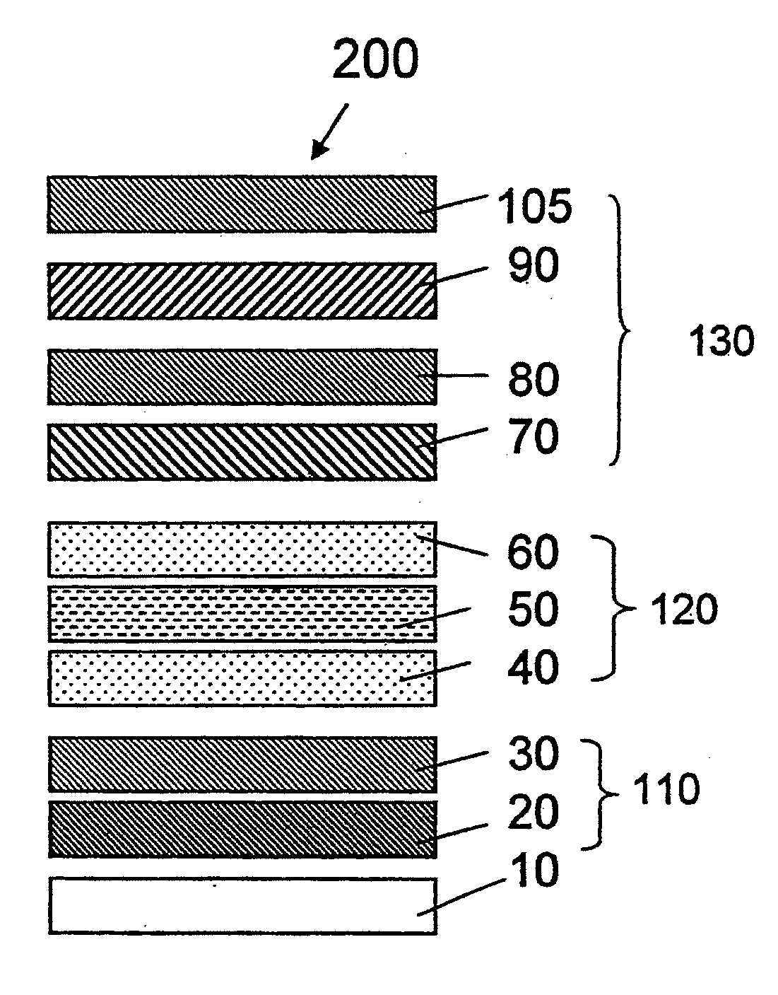
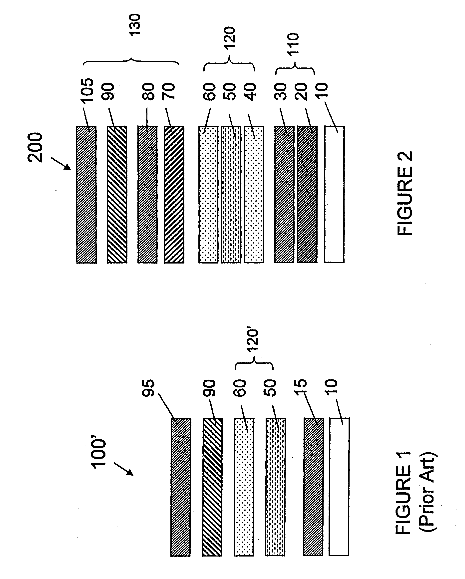
[0009]An electrically conductive multilayer stack having good IR reflection, EMP protection, radar attenuation, static discharge, weather resistance, and chemical stability is provided. Conceptually, the multilayer stack can be divided into three parts: a coated substrate; a primary conductive layer; and a secondary protective stack. Together, the coated substrate and primary conductive layer are similar to the multilayer stack shown in FIG. 1, with important differences noted herein. Together with the secondary protect stack, the three parts form an enhanced multilayer stack having greater durability and functionality.
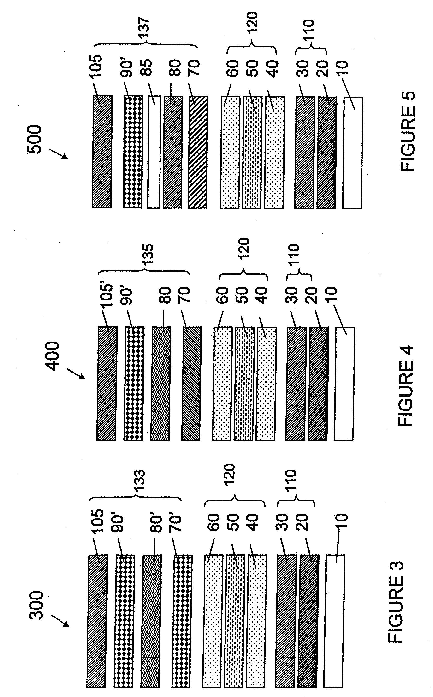
[0010]In one embodiment of the invention, a multilayer stack comprises a coated substrate, which includes a substrate (e.g., an aircraft canopy), a tie layer, and a base layer; a primary conductive layer, including first and second metal oxide layers with a metal layer sandwiched in between; and a protective stack, including a tie layer, a barrier layer, another tie layer, and a conductive topcoat or top layer. The primary conductive layer helps protect against lightning strikes. It also shields the substrate from electromagnetic interference (EMI) and provides radar attenuation. The multilayer stack generally has better conductivity and adhesion to a substrate.

Problems solved by technology

However, most polymeric materials are not infrared-reflective and do not meet the requirements for stealth jet fighters, such as low surface resistance (high electrical conductivity) and the ability to withstand extreme weather conditions.
While the prior art multilayer stack provides adequate infrared reflection, EMP protection, and radar attenuation to the canopy, its service life is limited due to delamination and the formation of blue spots on the multilayer stack.

Method used


Image

  • Conductive multilayer stack
  • Conductive multilayer stack
  • Conductive multilayer stack

Examples


example 1

[0053]A polycarbonate canopy is prepared and then lightly abraded to increase its surface roughness and surface area for receiving a primer (3-aminopropyltriethoxy silane, an adhesion promoter). The primer is gravity coated onto the canopy. Next, a polymeric solution (FX-430, produced by PPG Industries, Inc., Pittsburgh, Pa.) is applied to the canopy by flow coating. The polymeric solution is poured from the top of the canopy and from one end to another, allowing the solution to flow down and coat the canopy by gravity flow. Excess polymeric solution is allowed to flow down into a dripping pan and is collected for proper disposal.

[0054]After the entire outer surface of the canopy has been coated, it is cured in a heated oven at 220° F. for 4 hours. After the coating is cured, the canopy is abraded to increase its surface area for receiving the next coating layer. The abraded canopy is dusted and wiped clean, and then cleaned with an excess of Isopropanol (IPA) and dried thoroughly. ...


PUM

PropertyMeasurementUnit
Electrical conductivityaaaaaaaaaa
Concentrationaaaaaaaaaa
Electrical conductoraaaaaaaaaa

Abstract

An electrically conductive multilayer stack having good IR reflection, radar attenuation, static discharge, and other desirable properties includes a coated substrate, a primary conductive layer, and a secondary protective stack having greater durability and functionality then conventional multilayer stacks used to protect aircraft canopies and other substrates. The secondary protective stack includes at least one conductive layer that helps dissipate static charge.

Description

CROSS-REFERENCE TO RELATED APPLICATION[0001]This application claims the benefit of U.S. Provisional Application No. 61 / 137,643, filed Jul. 31, 2008, the disclosure of which is incorporated fully herein by reference.FIELD OF INVENTION[0002]This invention relates generally to transparent compositions and coated transparencies and laminates incorporating such compositions. More particularly, the invention relates to an electrically conductive coating stack having anti-static or static-dissipative properties.BACKGROUND OF THE INVENTION[0003]Modern jet aircraft canopies, such as F-22 stealth fighter canopies, are made of polymeric materials. Such materials are preferred because of their light weight, high strength, and ease of shaping. However, most polymeric materials are not infrared-reflective and do not meet the requirements for stealth jet fighters, such as low surface resistance (high electrical conductivity) and the ability to withstand extreme weather conditions. As a result, bot...

Claims


Application Information

Patent Timeline
IPC IPC(8): B32B15/04B32B9/04B32B27/40B32B27/38
CPCB64C1/1476C03C17/42Y10T428/31663Y10T428/31609Y10T428/31511
Inventor MARISCAL, JOSEBIMANAND, ALEXANDER
Owner PPG IND INC
Learn More