Mass air flow measurement device

a mass air flow and measurement device technology, applied in the direction of liquid/fluent solid measurement, instruments, structural/machine measurement, etc., can solve the problems of increasing the connection of wire harnesses, and the complicated connection between the control unit and the control device, so as to reduce the possibility of contamination, improve the performance, and reduce the amount of resource materials

Active Publication Date: 2010-02-11
HITACHI ASTEMO LTD
View PDF11 Cites 55 Cited by
  • Summary
  • Abstract
  • Description
  • Claims
  • Application Information

AI Technical Summary

Benefits of technology

[0025]As a measure against the above described anxieties, an arrangement is adopted in which the pressure intake pipe of the pressure sensing device is connected to the second bypass passage incorporating the humidity sensing device, that is, a pressure intake port is opened in the second bypass passage. Since the second bypass passage has a configuration such as not to take in contaminants, droplets of water and the like as described above, pressure taking-in from the second bypass passage can be performed with a reduced possibility of contamination of the pressure sensing device. Further, the pressure sensing device may be mounted in a position set as remote as possible from the second bypass passage to enable the pressure intake pipe to be formed longer so that the possibility of a contaminant or a droplet of water reaching the silicon diaphragm is close to zero. The position of the pressure sensing device in such a case is, for example, the outside of an outer wall surface of a member constituting the air intake tube.
[0026]Many people in the world are presently focusing their attention to environmental problems such as global warming. With above-described arrangement of the present invention, the number of component parts of internal combustion engine control devices can be reduced to contribute to reductions in the amounts of resource materials. Further, changes with time in various sensors including heating resistor type mass air flow measurement devices, humidity sensing devices, pressure sensing devices and temperature sensing devices can be reduced for the purpose of providing high-accuracy fuel control indispensable to both conformity with exhaust gas regulations and conformity with fuel consumption regulations for a long period of time. The present invention thus enables supply of an earth-friendly, low-fuel-consumption, clean-exhaust-gas engine control system to the market.
[0027]More specifically, as a result of connection of the second bypass passage to the bypass passage, a configuration improved both in terms of performance and in terms of reliability in humidity measurement can be provided to increase the flow rate in the second bypass passage without taking any contaminant or any droplet of water into the second bypass passage.

Problems solved by technology

Also, wire harnesses which connect such various sensors and control devices, a control unit for controlling the sensors and control devices to each other are considerably complicated.
However, various technical problems will arise with further integration of other devices such as the above-mentioned pressure sensing device and humidity sensing device in future.
In particular, no practical use in fuel control has been made of any humidity sensing device corresponding to that mentioned above.
For use in engine control, for example, in a state of being integrated with the above-mentioned heating resistor type mass air flow measurement device and sensors or the like, however, a hostile-environment performance equivalent to that of the heating resistor type mass air flow measurement device is required.
An environment hostile to a humidity sensing device in particular is an environment in which a sensing element portion can be contaminated or a droplet of water can attach to a humidity sensing element portion as a result of dew condensation or permeation of rainwater.

Method used


Image

  • Mass air flow measurement device
  • Mass air flow measurement device
  • Mass air flow measurement device

Examples


Embodiment Construction

[0077]Embodiments of the present invention will be described below.

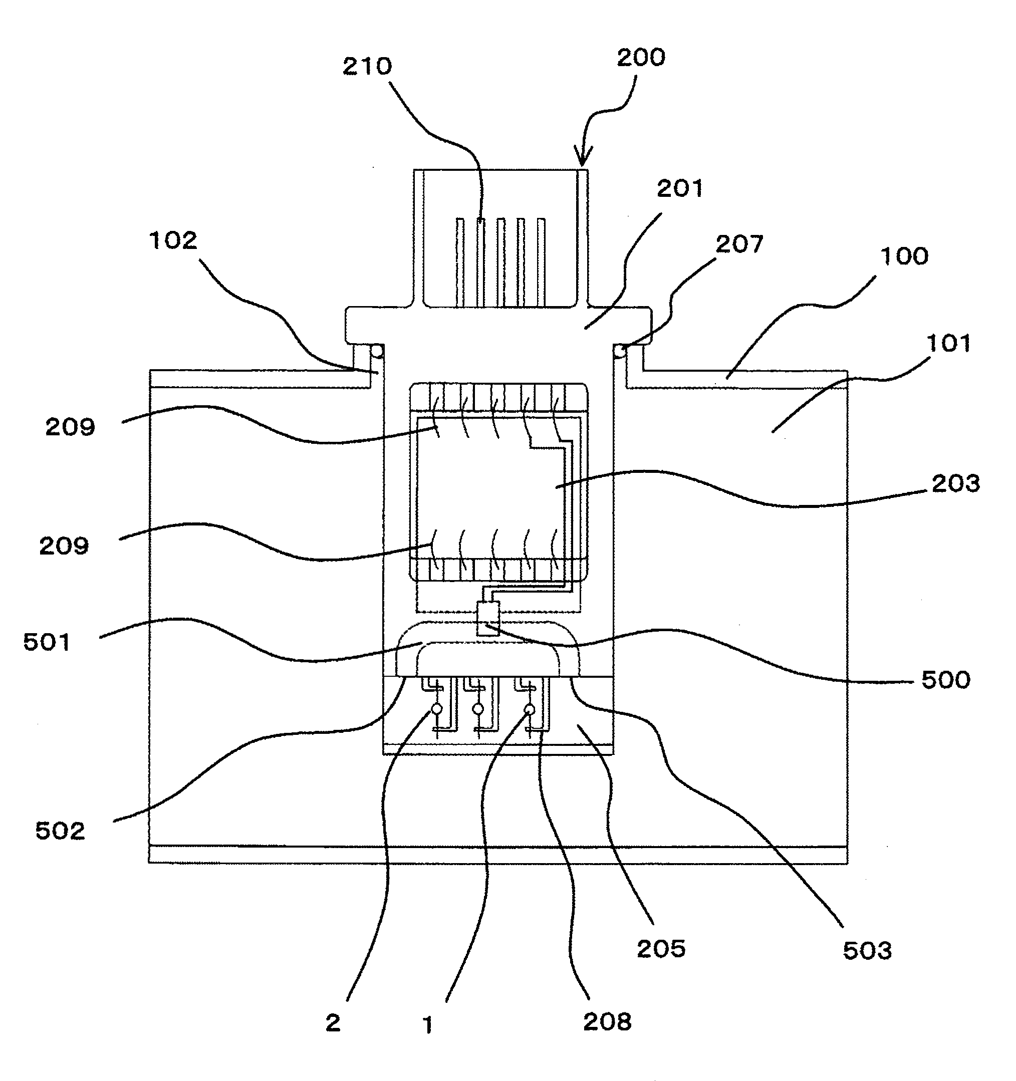
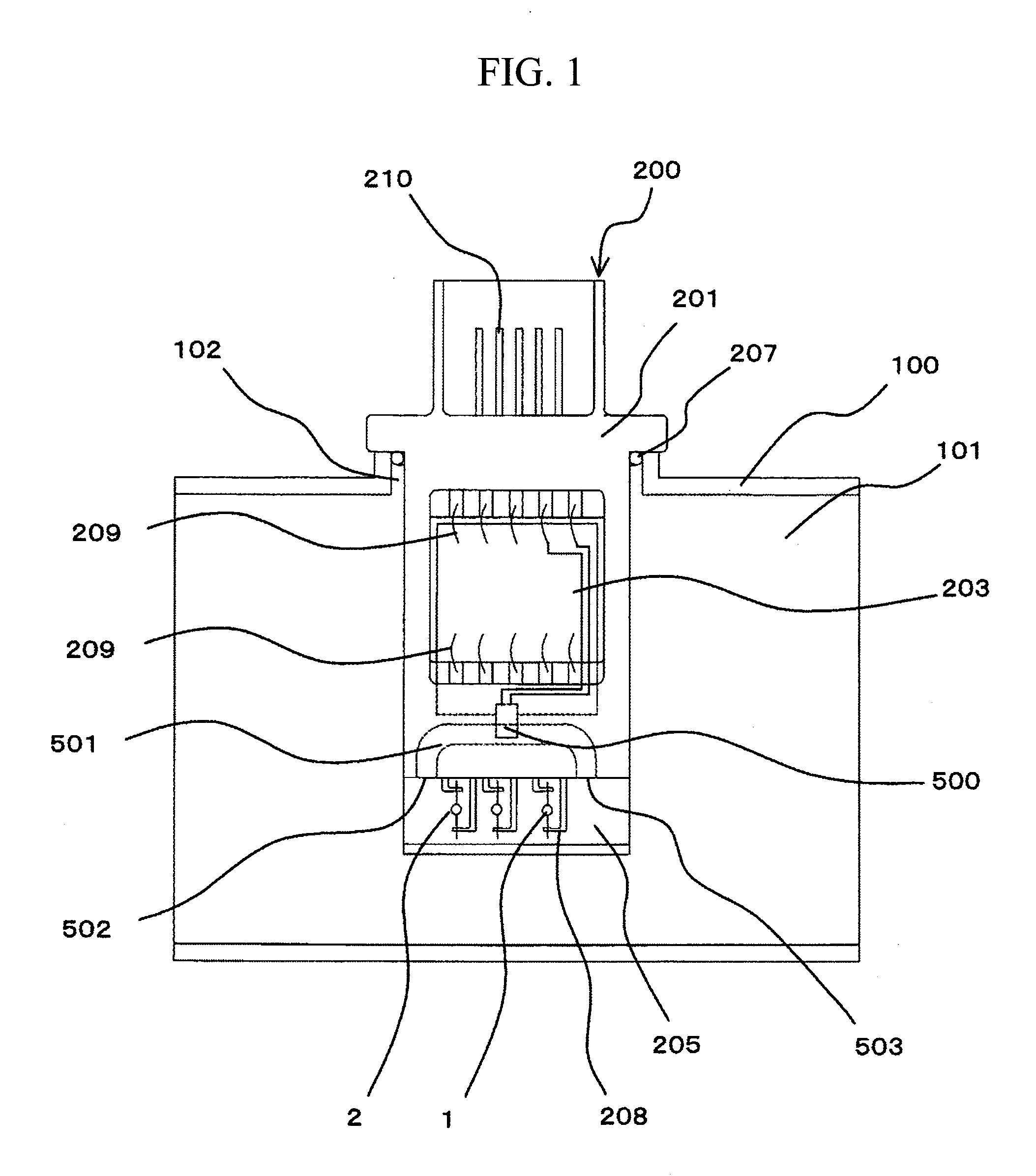
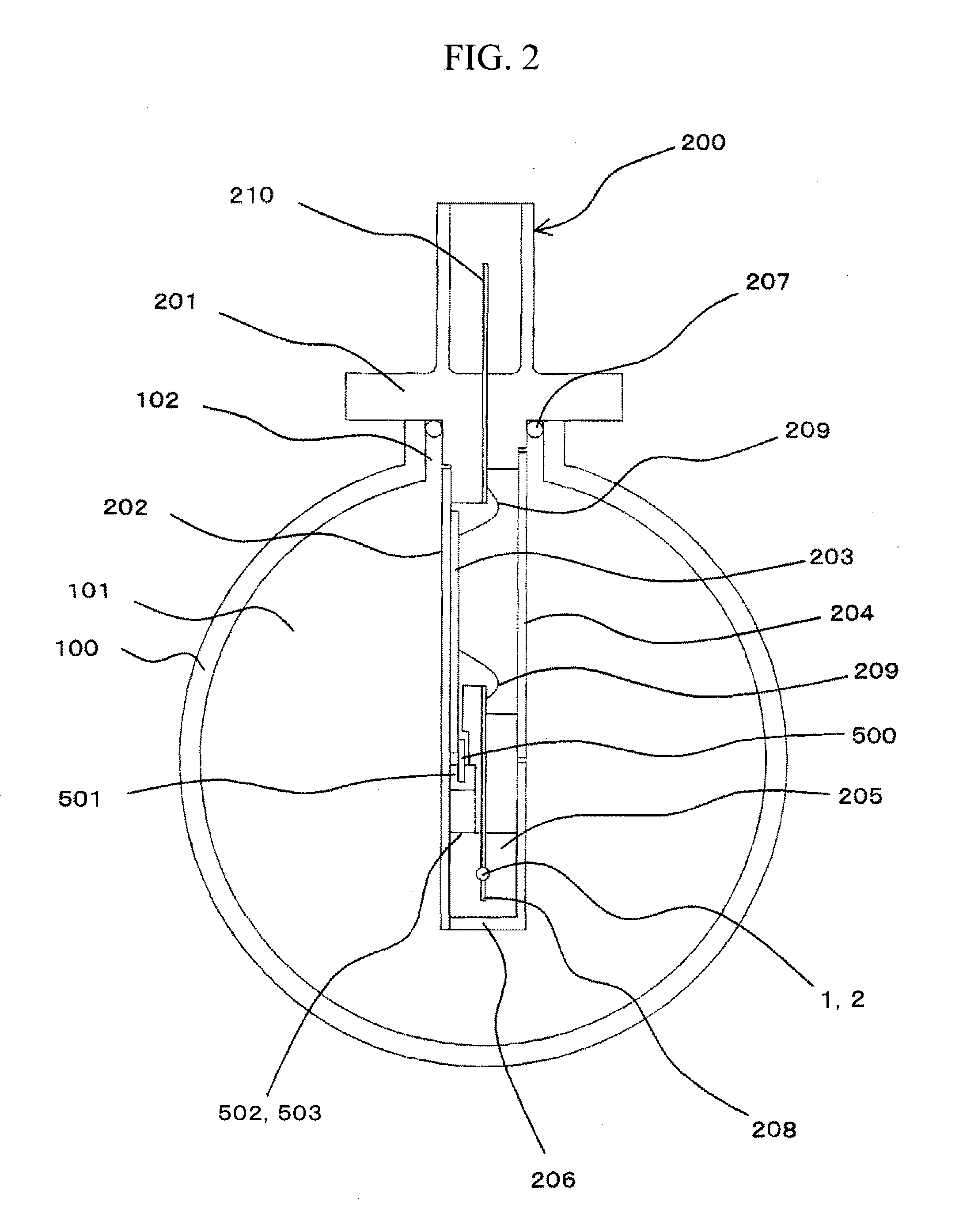
[0078]A concrete example of an arrangement according to the present invention will be described with reference to FIGS. 1 and 2. FIG. 2 is a front view of the arrangement shown in FIG. 1.

[0079]In a portion of a flow tube member (intake tube member) 100 forming a main flow passage (also referred to as an intake passage or simply as an intake tube) 101, a device insertion slot 102 in which a portion of a heating resistor type mass air flow measurement device 200 is inserted is provided. The heating resistor type mass air flow measurement device 200 integrally incorporating a humidity sensing device 500 is placed in the device insertion slot 102. A housing member 201 provided as a case member for the heating resistor type mass air flow measurement device 200 is attached to the intake tube member 100 to function.

[0080]Members constituting the heating resistor type mass air flow measurement device 200 as well as the housi...


PUM


Abstract

An arrangement of a mass intake air flow measurement device suitable for integrating a humidity sensing device as well as a temperature sensing device and a pressure sensing device is provided. A second bypass passage 501 bypassing a bypass passage 205 is formed and a humidity sensing device 500 is mounted in the second bypass passage 501. A second bypass passage inlet 502 and a second bypass passage outlet 503 formed in a wall surface of the bypass passage 205 are opened parallel to the direction of flow of air flowing in the bypass passage 205.

Description

BACKGROUND OF THE INVENTION[0001]1. Field of the Invention[0002]The present invention relates to a heating resistor type mass air flow measurement device suitable for measuring the flow of intake air in an internal combustion engine and to an internal combustion engine using the mass air flow measurement device.[0003]2. Background Art[0004]A heating resistor type mass air flow measurement device is known as a flow measurement art for internal combustion engines (see JP Patent No. 3523022). This device utilizes a correlation between an inflow and the amount of heat removed from a heating resistor and is capable of directly measuring the mass flow required in engine combustion control. Therefore this device is being widely used as a flowmeter for air / fuel ratio control especially in motor vehicles.[0005]As a sensor formed by integrating, for example, a flow measurement device, a pressure sensing device and a humidity sensing device for an internal combustion engine and capable of meas...

Claims


Application Information

Patent Timeline
Patent Type & Authority Applications(United States)
IPC IPC(8): G01M15/04G01F1/68
CPCG01F5/00G01F1/6842H01L2224/48091H01L2924/00014
Inventor SAITO, TAKAYUKIYOHO, TAKAYUKIIGARASHI, SHINAYAKIKAWA, HIROMU
Owner HITACHI ASTEMO LTD
Why Eureka
Try Eureka