Sample handling device for and a method of handling a sample

a technology for handling devices and samples, applied in sampling, measurement devices, instruments, etc., can solve the problem of time-consuming operation of such devices, and achieve the effect of efficient handling of samples

Inactive Publication Date: 2010-02-11
QINSTRUMENTS GMBH
View PDF5 Cites 49 Cited by
  • Summary
  • Abstract
  • Description
  • Claims
  • Application Information

AI Technical Summary

Benefits of technology

[0026]According to an exemplary embodiment, an apparatus, particularly for applications in the field of life science, may be provided in which a base part and a cover part may be tilted with respect to one another under the influence of two different forces, thereby allowing to modify the volume of a sample space enclosed between the base part and the cover part. Consequently, capillary forces and other interactions may be varied, since such capillary forces are usually more effective or relevant in case of a small angle between base part and cover part as compared to a scenario in which the angle between base part and cover part is larger. Therefore, (fluidic) sample material can be transported into or out of the sample space using capillary forces and other interactions, allowing to automate sample supply and sample draining / carrying off. This may allow to use the sample handling device particularly for high throughput screening applications without the need that a human user has to spend a lot of operating time for operating the device, and many samples can be tested with such an automated sample handling system in a short time.
[0114]The injection opening may be located essentially at a pivoting axis around which the base part and the cover part may be tiltable with regard to one another. This geometrical arrangement may allow for a proper insertion of the fluidic sample into the sample space.

Problems solved by technology

However, operation of such devices may be time consuming in a scenario in which large numbers of samples shall be analyzed, for instance for high-throughput screening.

Method used


Image

  • Sample handling device for and a method of handling a sample
  • Sample handling device for and a method of handling a sample
  • Sample handling device for and a method of handling a sample

Examples


Embodiment Construction

[0135]The illustration in the drawing is schematically. In different drawings, similar or identical elements are provided with the same reference signs.

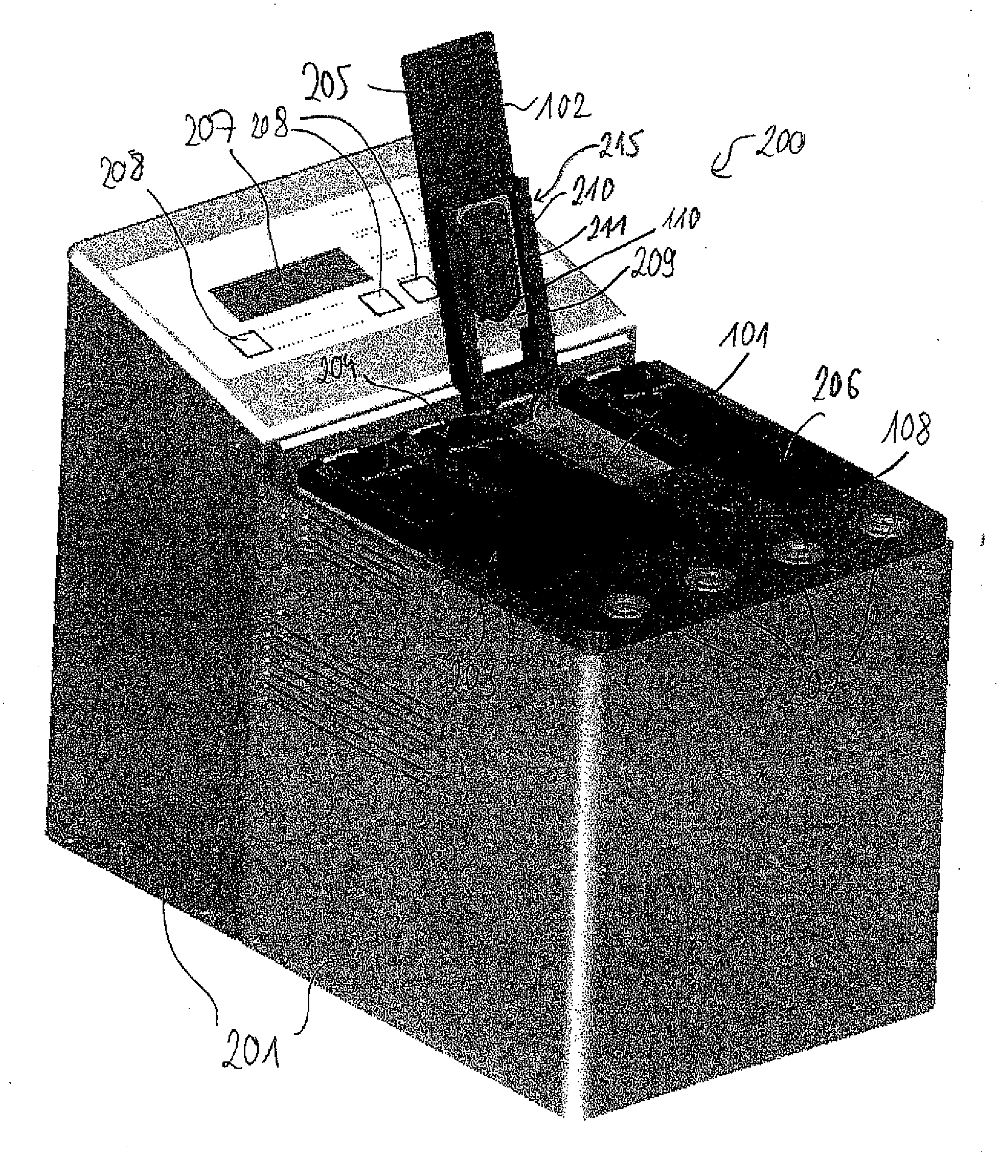
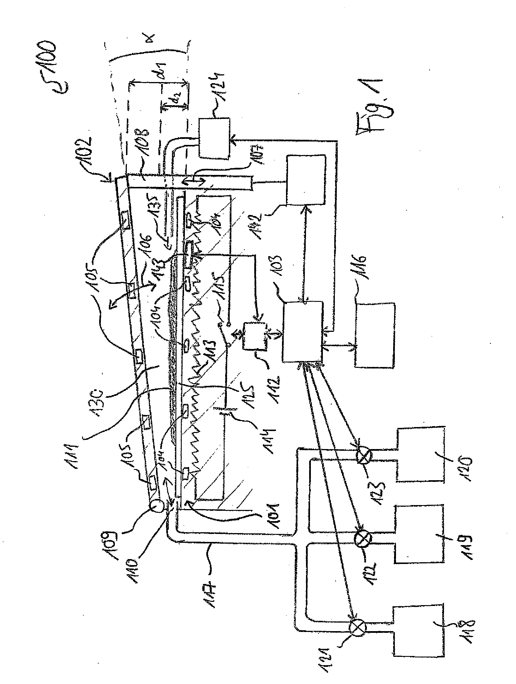
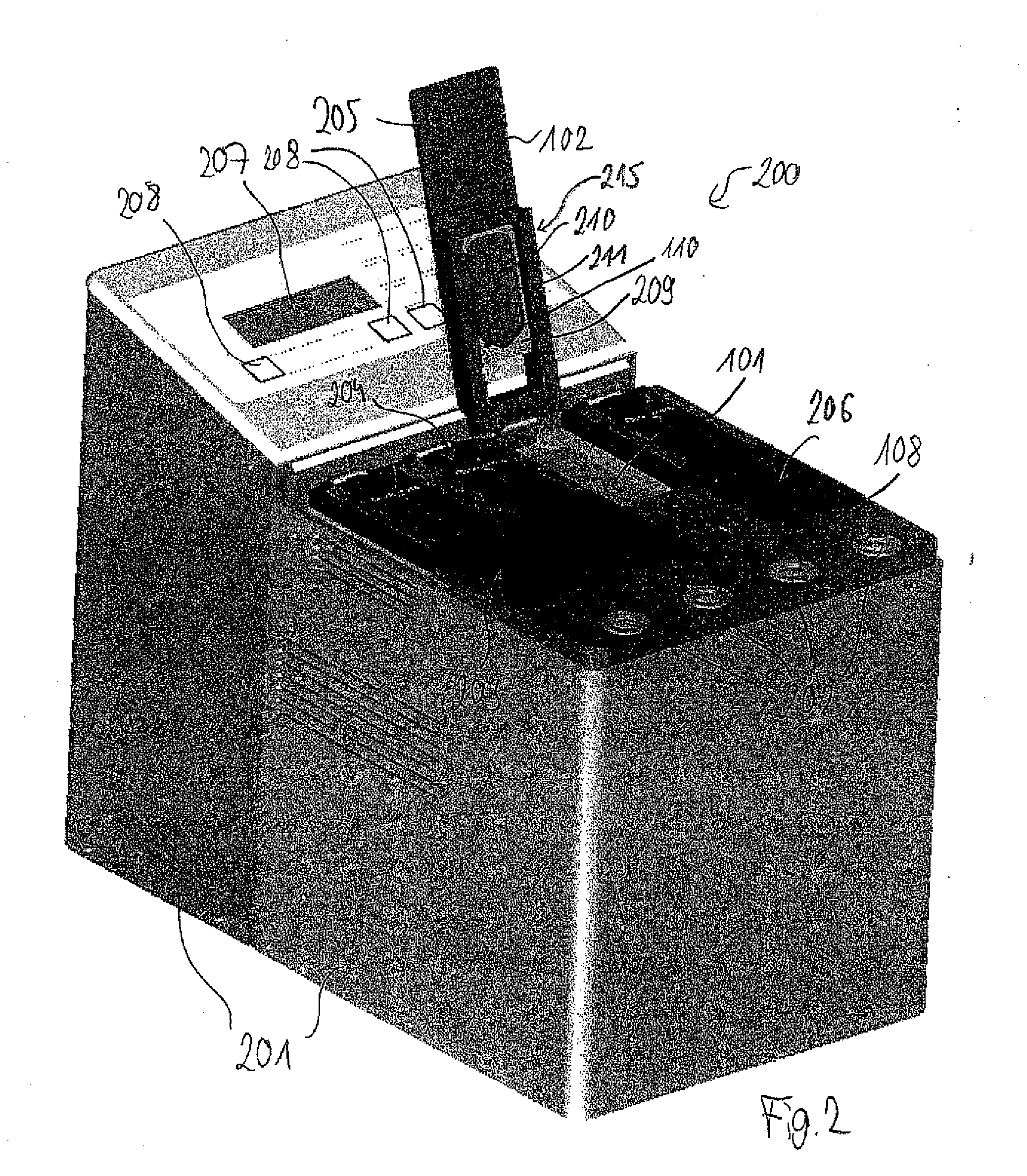
[0136]In the following, referring to FIG. 1, a sample handling device 100 according to an exemplary embodiment of the invention will be explained.

[0137]The sample handling device 100 comprises a base part 101 and a cover part 102. Furthermore, a first force generating unit is provided which will be described in more detail in the following and which is adapted to generate an attracting magnetic force promoting attraction between the base part 101 and the bottom part 102. Beyond this, a second force generating unit which will be described in the following in more detail is provided and which is adapted to generate a counterforce having a component being oriented opposite to the attracting force to promote a motion of the base part 101 and the cover part 102 relative to each other.

[0138]Furthermore, a central processing unit 103 (CPU) ...


PUM

PropertyMeasurementUnit
temperaturesaaaaaaaaaa
vertical sizeaaaaaaaaaa
sizeaaaaaaaaaa

Abstract

A sample handling device (100) for handling a sample, the sample handling device (100) comprising a base part (101), a cover part (102), a first force generating unit (104, 105) adapted to generate an attracting force promoting attraction between the base part (101) and the cover part (102), a second force generating unit (108, 142) adapted to generate a counterforce having at least a component being oriented opposite to the attracting force to promote a motion of the base part (101) and the cover part (102) relative to each other, and a control unit (103) adapted for controlling the second force generating unit (108, 142) for moving the base part (101) and the cover part (102) relative to each other for influencing a sample space (130) between the base part (101) and the cover part (102) for accommodating the sample.

Description

[0001]This application claims the benefit of the filing date of European Patent Application No. 06116645.0 filed Jul. 5, 2006, of U.S. Provisional Patent Application No. 60 / 806,571 filed Jul. 5, 2006, and of U.S. Provisional Patent Application No. 60 / 795,099 filed Apr. 26, 2006, the disclosure of which is hereby incorporated herein by reference.FIELD OF THE INVENTION[0002]The invention relates to a sample handling device for handling a sample.[0003]Moreover, the invention relates to a module for a sample handling device.[0004]The invention further relates to a method of handling a sample.[0005]Moreover, the invention relates to a program element.[0006]Further, the invention relates to a computer-readable medium.[0007]Beyond this, the invention relates to an insert element.BACKGROUND OF THE INVENTION[0008]Biochemical analysis systems for supplying, handling, and analyzing samples are important in the field of life science.[0009]WO 2001 / 51909 discloses specimen slide preparation using...

Claims


Application Information

Patent Timeline
Patent Type & Authority Applications(United States)
IPC IPC(8): G01N1/31
CPCG01N1/312G01N1/2813
Inventor HOYER, OLAF
Owner QINSTRUMENTS GMBH
Why Eureka
Try Eureka