Composite tool for molding cylindrical parts

Active Publication Date: 2010-02-11
CONSTR NAVALES & IND DE LA MEDITERRANEE CNIM
View PDF36 Cites 29 Cited by
  • Summary
  • Abstract
  • Description
  • Claims
  • Application Information

AI Technical Summary

Benefits of technology

[0053]the tool of the invention comprises a coating in a composite of carbon fibers pre-impregnated with an epoxy resin or with a polyimide structure resin, notably in bismaleimide, so that the surface of the tool may be machined without deforming it and while retaining the homogeneity and the seal of the material;
[0054]the tool may be repaired according to a simple procedure which may be individually applied to each component of the tool;
[0055]the tough

Problems solved by technology

Although the Invar technology is widely used in mass production, it is nevertheless a fact that the unit cost of such a mold is high.
In return, toolings made in carbon fibers are less expensive, but they are more fragile and practically unrepairable, and this mainly because of problems of leaks which subsist after their repair.
When the matter is of making cylindrical parts, notably with large dimensions, the problems for their making originate less from their size and from difficulties in handling such molds, but rather from the difficulty of guaranteeing the final geometrical tolerance

Method used


Image

  • Composite tool for molding cylindrical parts
  • Composite tool for molding cylindrical parts
  • Composite tool for molding cylindrical parts

Examples


Embodiment Construction

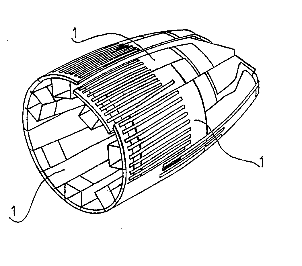
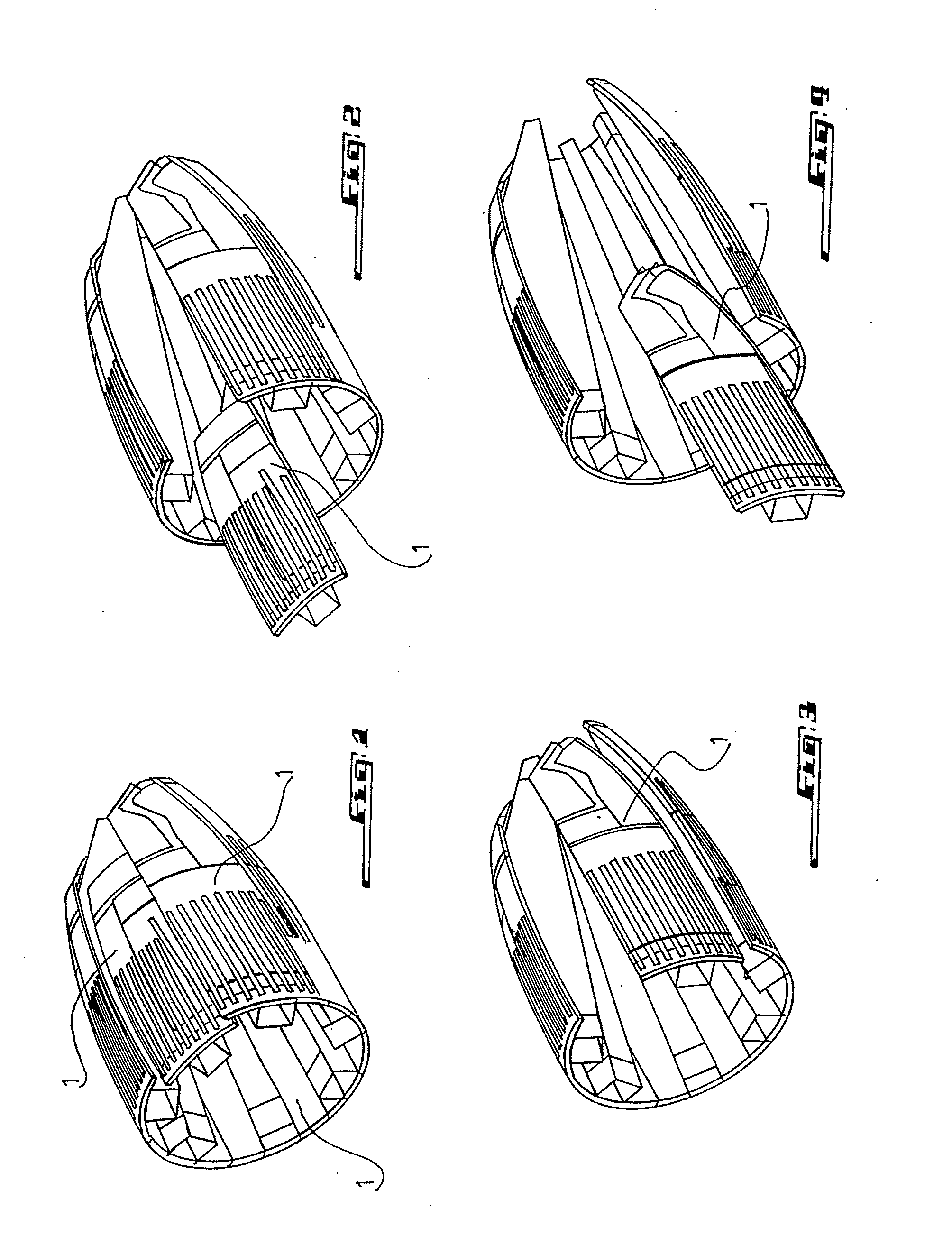
[0071]FIG. 1 illustrates a tool in a composite material for making a cylindrical part in a composite material, e.g. for making a fuselage component of an aircraft. The tool, which is itself made as an axisymmetrical cylindrical component, is intended to form a mandrel on which the cylindrical part to be made will be formed.

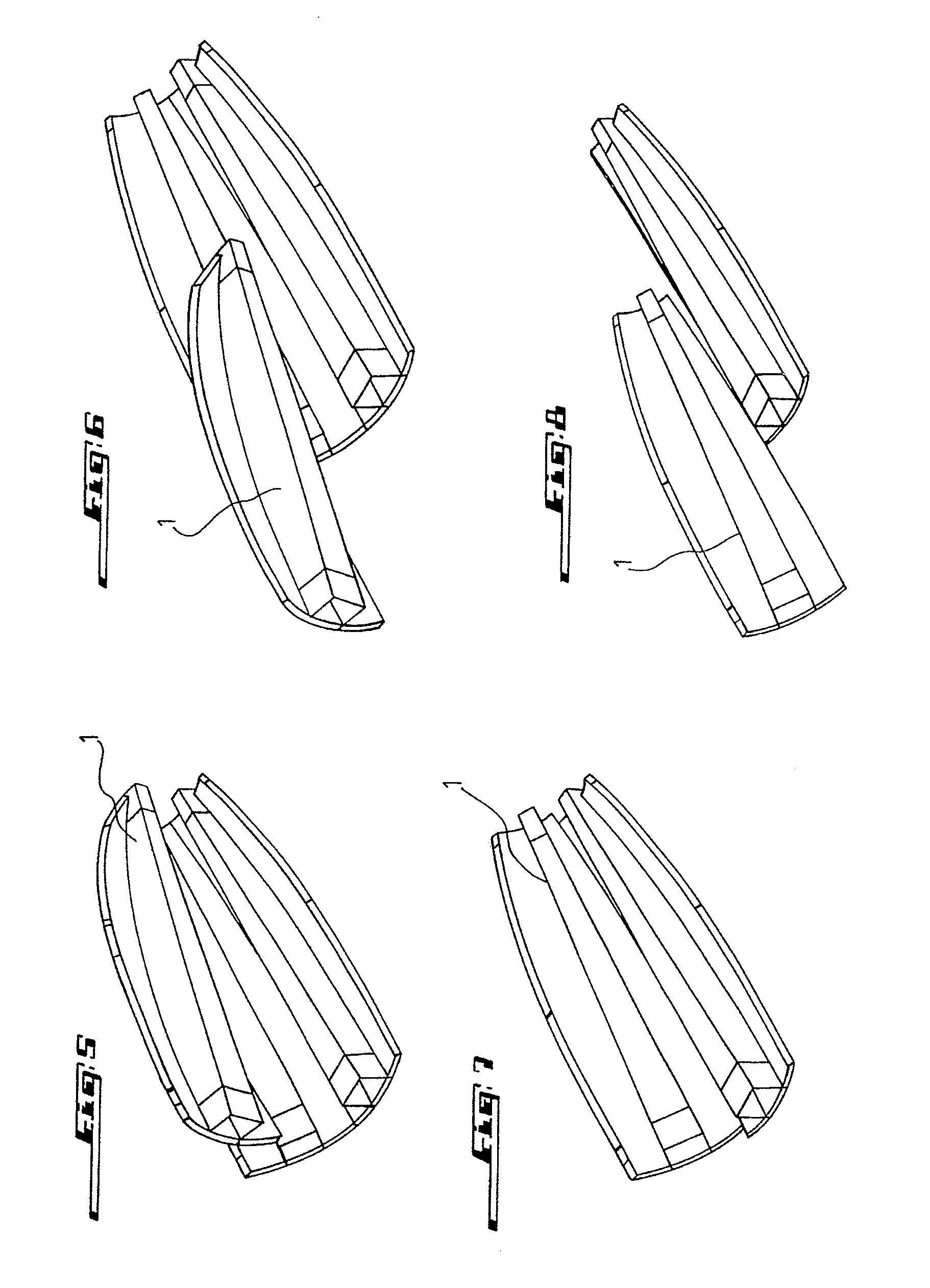
[0072]According to the invention, the tool comprises seven components, each of which forms a cylindrical sector of the tool. The components 1 are conformed in order to be maintained in leakproof contact along the perimeter of the part to be made.

[0073]Advantageously, the components 1 of the tool of the invention are all identical with each other when the question is to make axisymmetrical cylindrical parts or with a shape close to that of an axisymmetrical cylinder.

[0074]However, the present invention also applies to tools in a composite material with which tubular parts having a non-circular section may be made.

[0075]For this reason, the number of components and,...


PUM

PropertyMeasurementUnit
Structureaaaaaaaaaa

Abstract

A tool of a composite material for making a cylindrical part of a composite material. The tool is used for forming a mandrel on which the cylindrical part is to be formed. The tool comprises a set of members, each member defining a cylindrical sector of the tool, each member having a bearing structure of a fiber composite and a skin molded on the bearing structure. The tool further includes a seal located at the junctions between the tool members.

Description

FIELD OF THE INVENTION[0001]The present invention relates to a tool in a composite material for making a cylindrical part in a composite material. The invention also relates to a method for making such a tool.BACKGROUND[0002]In the aeronautical field, for only mentioning a single field of application, carbon fiber composite parts are increasingly used for obtaining more and more lightweight structures without however abandoning rigidity and other required characteristics, but also for obtaining components which have a more pleasant aspect than a metal part while providing fire resistance.[0003]The making of such composite parts requires high precision tooling. This tooling which may also be called a mold, should both provide the usual functions of any tooling, as recalled hereafter, guarantee geometrical tolerances of the final part and sometimes withstand rather particular thermal and pressure cycles such as those which are involved for example upon passing into an autoclave.[0004]...

Claims


Application Information

Patent Timeline
IPC IPC(8): B29C65/70B29C33/42
CPCB29C33/38B29C33/3842B29C33/485B29C70/342B29C70/446B29K2079/08B29K2707/04B29L2031/26B29C33/301B29K2063/00B29C33/30
Inventor MICHEAUX, DOMINIQUEVALIBOUSE, PIERREMARINO, PHILIPPECOLOMBO, DENIS
Owner CONSTR NAVALES & IND DE LA MEDITERRANEE CNIM
Why Eureka
Try Eureka