Horn Antenna with Integrated Impedance Matching Network for Improved Operating Frequency Range

a horn antenna and impedance matching technology, applied in the field of horn antennas with integrated impedance matching networks, can solve the problems of reducing the service life of the horn antenna, so as to reduce the mismatch effect of impedan

Active Publication Date: 2010-02-11
TDK CORPARATION
View PDF16 Cites 66 Cited by
  • Summary
  • Abstract
  • Description
  • Claims
  • Application Information

AI Technical Summary

Benefits of technology

[0017]The problems outlined above may be in large part addressed by a dual- or quad-ridged horn antenna including at least one pair of ridges arranged opposite one another for guiding an electromagnetic wave there between. A transmission line is coupled to a first one of the ridges for supplying power to, or receiving a signal from, a feed region of the horn antenna. To reduce impedance mismatches between the transmission line and the ridges, an impedance matching network is embedded within a second one of the ridges at the feed region. In general, the impedance matching network may be configured for reducing mismatch by providing a series capacitance between the transmission line and the ridges at the feed region.

Problems solved by technology

As such, the antenna gain will be less than the directivity for real antenna designs, which provide less than 100 percent radiation efficiency.
However, conventional dual-ridged horn designs are currently unable to provide a useable radiation pattern over a bandwidth significantly greater than 18:1.
The bandwidth limitation is further exacerbated in quad-ridged horn designs.
In a practical situation, coupling between the two modes, especially in the feed region, is inescapable and detracts from the quad-ridged horn antenna's performance.
Because of various difficulties in implementing the feed region (e.g., space constraints), quad-ridged horns have not been able to provide the same bandwidth as dual-ridged, single-polarization horns.

Method used


Image

  • Horn Antenna with Integrated Impedance Matching Network for Improved Operating Frequency Range
  • Horn Antenna with Integrated Impedance Matching Network for Improved Operating Frequency Range
  • Horn Antenna with Integrated Impedance Matching Network for Improved Operating Frequency Range

Examples


Embodiment Construction

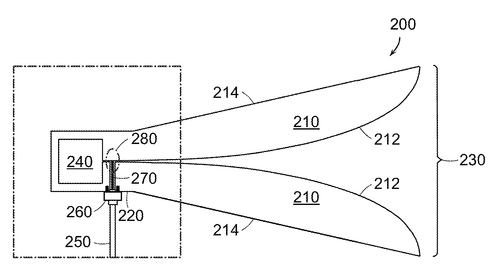
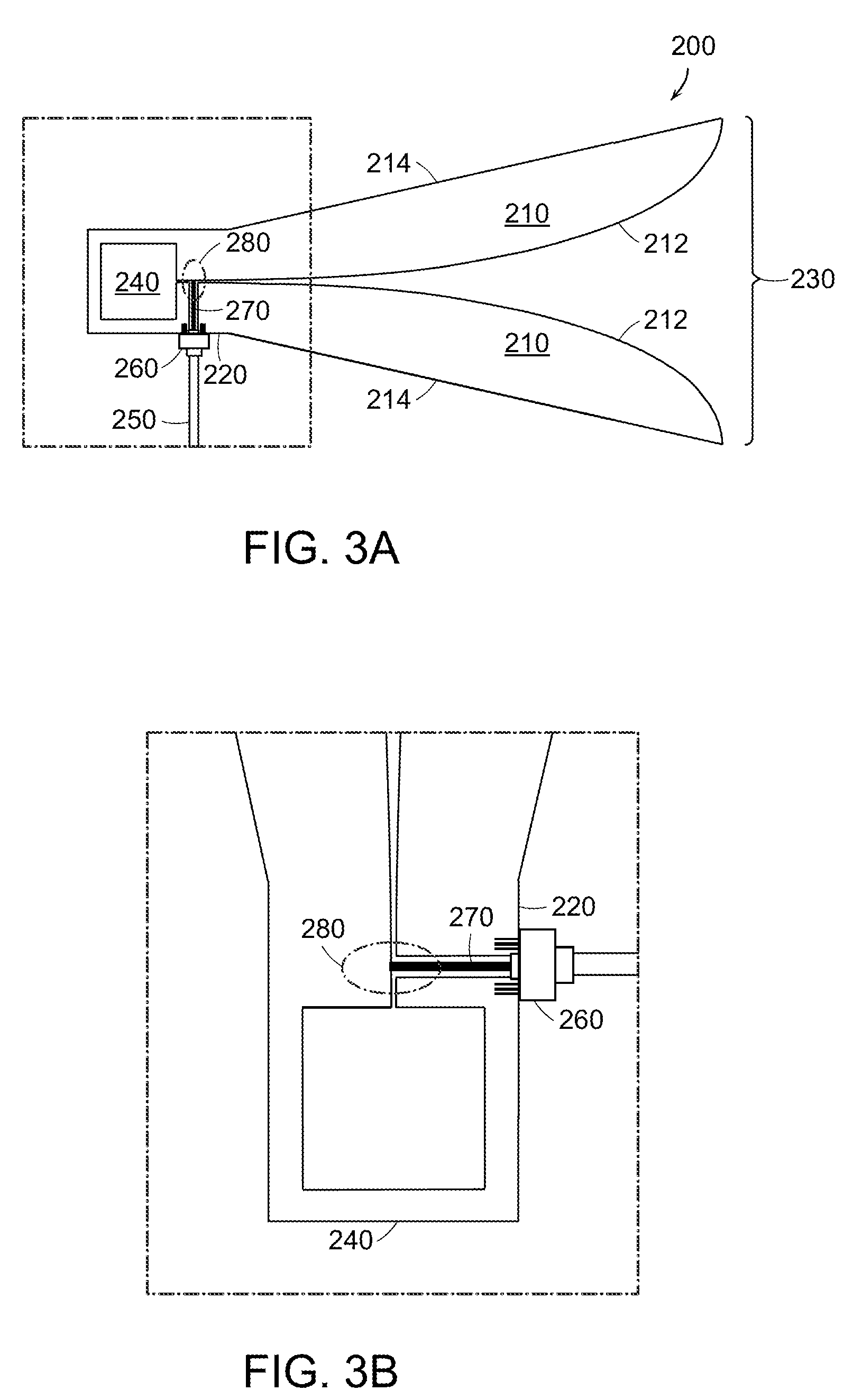
[0044]Turning to the drawings, exemplary embodiments of a dual-ridge horn antenna are shown in FIGS. 3 and 5. As will be described in more detail below, the antenna design provided herein improves upon conventional designs by embedding an impedance matching network within at least one “ridge” of a dual- or quad-ridged horn antenna. The impedance matching network improves the operating frequency range at the low end by reducing impedance mismatch between the coaxial transmission line and the ridge(s) at the feed point. In a general embodiment, the impedance matching network may include a conductive feed line or conductive pin, which extends from the coaxial transmission line, through a first one of the ridges and into a notch formed within a second one of the ridges. The length and diameter of the conductive pin may be chosen, so that the conductive pin does not make physical contact with the ridges, but instead, couples indirectly through capacitive coupling. In some embodiments, a ...


PUM


Abstract

A dual- or quad-ridged horn antenna with an embedded impedance matching network is provided herein. According to one embodiment, the horn antenna may include at least one pair of ridges arranged opposite one another for guiding an electromagnetic wave there between. A transmission line is coupled to a first one of the ridges for supplying power to, or receiving a signal from, a feed region of the horn antenna. To reduce impedance mismatches between the transmission line and the ridges, an impedance matching network is embedded within a second one of the ridges at the feed point. The impedance matching network reduces impedance mismatch and extends the operational frequency range of the horn antenna by providing a sufficient amount of series capacitance between the transmission line and the ridges at the feed region. As set forth herein, the impedance matching network is preferably implemented as an open-circuit transmission line stub or capacitive stub.

Description

BACKGROUND OF THE INVENTION[0001]1. Field of the Invention[0002]This invention relates to antenna design and, more particularly, to broadband horn antennas with integrated impedance matching networks.[0003]2. Description of the Related Art[0004]The following descriptions and examples are not admitted to be prior art by virtue of their inclusion within this section.[0005]An antenna is a device which can radiate or receive electromagnetic (EM) energy. An ideal transmitting antenna receives power from a source (e.g., a power amplifier) and radiates the received power into space. That is, electromagnetic energy escapes from the antenna and, unless reflected or scattered, does not return. A practical antenna, however, generates both radiating and non-radiating EM field components. An example of a non-radiating EM field component would be the portion of the accepted power that is returned to the source, or otherwise dissipated in a resistive load.[0006]The performance of an antenna can be...

Claims


Application Information

Patent Timeline
Patent Type & Authority Applications(United States)
IPC IPC(8): H01Q13/02
CPCH01Q13/0275H01Q13/085H01Q13/02H01Q13/06
Inventor MCLEAN, JAMES S.
Owner TDK CORPARATION
Why Eureka
Try Eureka