
Method and plant for co2 enrichment

a technology of co2 enrichment and plant, which is applied in the direction of auxillary pretreatment, absorption, and using liquid separation agents, to achieve the effects of reducing the volume of gas, increasing the partial pressure, and being efficient and less expensiv

Inactive Publication Date: 2010-02-18
SARGAS
View PDF10 Cites 15 Cited by
  • Summary
  • Abstract
  • Description
  • Claims
  • Application Information

AI Technical Summary

Benefits of technology

[0036]The large gas volume and low concentration of CO2 are two main obstacles in the capture of CO2 from industrial plants and thermal power plants. Enrichment of CO2 from a CO2 containing gas before capturing the CO2 makes it possible to achieve a more efficient and less expensive capture of CO2 from the exhaust gas.
[0037]Steps d) and e) may repeated one or more times to allow for a higher degree of enrichment of CO2 to reduce the volume of the gas and to increase the partial pressure, or concentration of CO2, in the gas to be treated during the CO2 capturing process, to increase the efficiency of the capturing process even more.
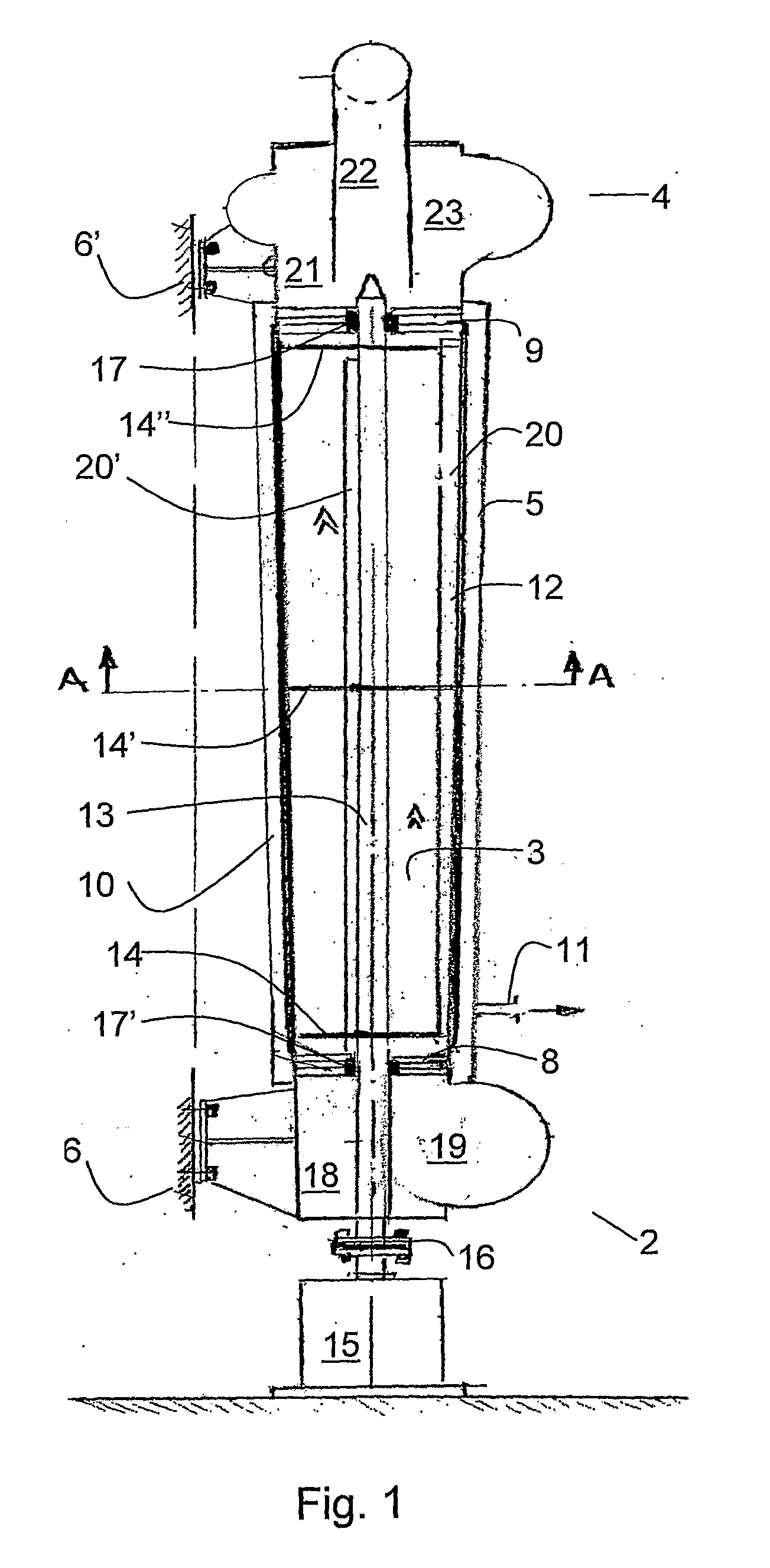
[0062]According to one embodiment, the plant comprises two or more rows or serially connected centrifuges or cyclones arranged in parallel. Arranging the centrifuges or cyclones in parallel makes it possible to increase the capacity of the enrichment plant.

Problems solved by technology

The large gas volume and low concentration of CO2 are two main obstacles in the capture of CO2 from industrial plants and thermal power plants.

Method used


Image

  • Method and plant for co2 enrichment
  • Method and plant for co2 enrichment
  • Method and plant for co2 enrichment

Examples


example 1

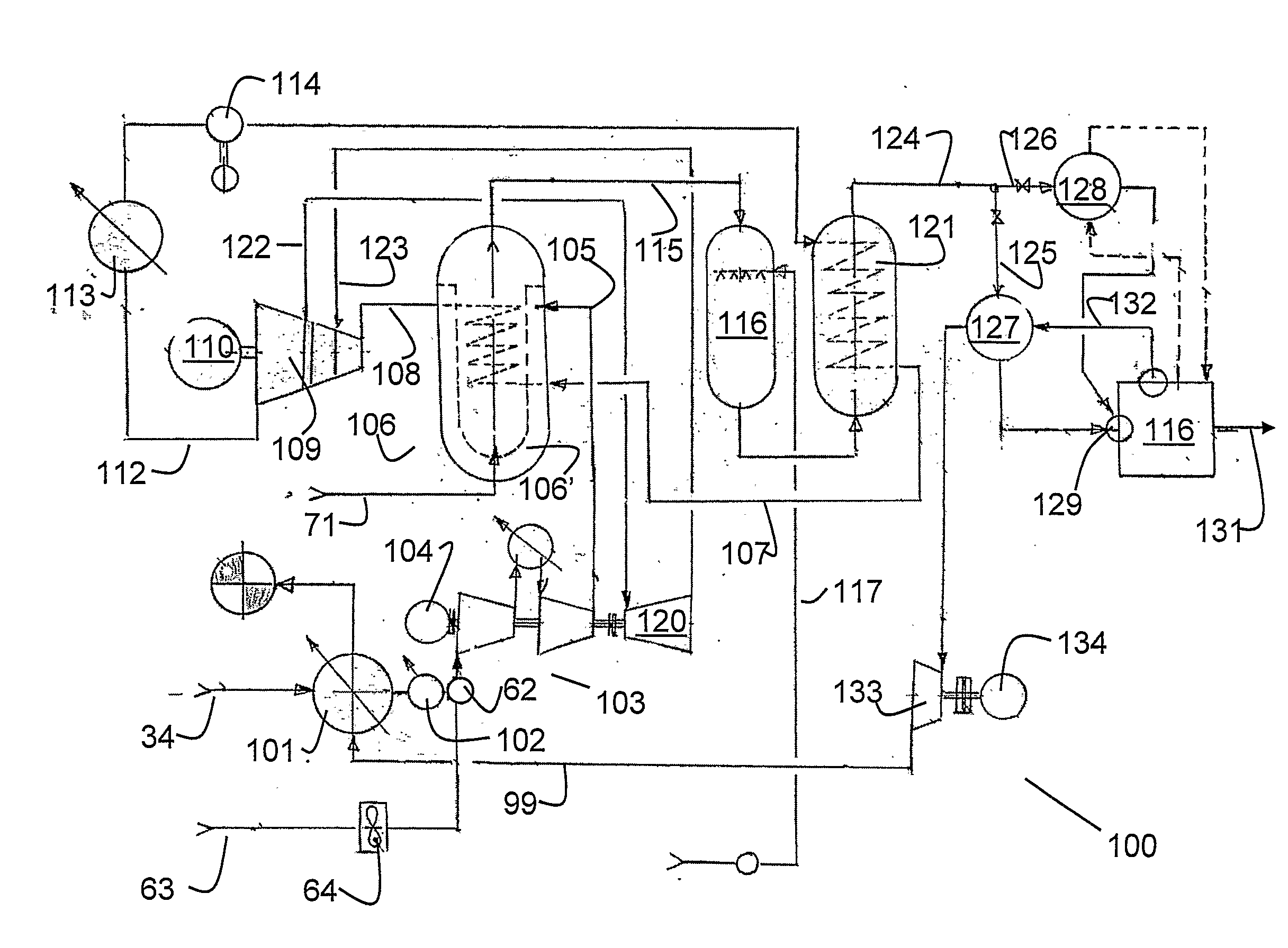
[0106]FIG. 5 illustrates a combined heat and power plant 80 connected to a CO2 enrichment plant 81. The combined power and heat plant 80 is illustrated by a gas turbine 82, heat exchange means 83 and a flue gas manifold 30. A plurality of centrifuges 1, 1′, 1″, 1′″ are connected in centrifuge trains in which four centrifuges are connected in series. Several compressor trains are parallel arranged between the flue gas manifold and a light gas manifold 33 and a manifold for CO2 enriched gas 34 as described with reference to FIG. 3.

[0107]The plant according to this example comprises two units according to FIG. 5, in a plant as illustrated in FIG. 4. Each unit according to FIG. 5, comprises a 130 MW gas turbine, resulting in a exhaust gas flow of 400 m3 / sec, giving a total effect of 260 MW and a total exhaust gas volume of 800 m3 / sec.

[0108]Each unit has its own CO2 enrichment plant 81 comprising 5 parallel centrifuge trains, each with four centrifuges in series. The centrifuges are pref...

example 2

[0145]FIG. 7 illustrates an exemplary plant for treatment of flue gas from an aluminum factory 150. Flue gas from the aluminum factory 150 is introduced as a fuel into a ground burner 151 through a line 152. The flue gas contains CO that is used as fuel in the ground burner and is burned at a temperature above 700° C. Air is introduced through an air line 153 into a cooling mantle 154 partly surrounding the ground burner 151, an exhaust gas line 155 for transferring exhaust gas from the ground burner to a economizer 156, and the economizer to cool the economizer, the transfer line and a part of the ground burner. The heated air in the mantle is then introduced into the ground burner as oxygen containing gas for the combustion therein.

[0146]A gas burner 157, fed by natural gas from gas line 158 and air from air line 159, is provided in the ground burner 151, both to ignite the ground burner to start the combustion of CO, and to withheld a temperature high enough to ascertain combusti...


PUM

PropertyMeasurementUnit
mean temperatureaaaaaaaaaa
partial pressureaaaaaaaaaa
pressureaaaaaaaaaa

Abstract

The present invention relates to a method and a plant for CO2 enrichment of a CO2 containing gas, such as an exhaust gas from an industrial plant or a thermal power plant, by means of serially connected centrifuges of cyclones. Enrichment of CO2 reduces the volume of the exhaust gas, increases the partial pressure of CO2 therein and makes a less expensive and more effective capture of CO2 possible. The invention also relates to plants for carrying out the method.

Description

THE FIELD OF THE INVENTION [0001]The present invention relates to a method and a plant for CO2 enrichment of a CO2 containing gas. More specifically, the present invention relates to a method and a plant for increasing enrichment of CO2, or for increasing the partial pressure of CO2 in a gas stream comprising CO2 in combination with other gases, such as flue gases from industrial processes and combustion of fossil fuels, to make a subsequent CO2 capturing more efficient. The invention also relates to a method and a plant for capturing CO2 from a CO2 containing gas including said method and plant for CO2 enrichment.BACKGROUND [0002]The concentration of CO2 in the atmosphere has increased by nearly 30% in the last 150 years. The concentration of methane has doubled and the concentration of nitrogen oxides has increased by about 15%. This has increased the atmospheric greenhouse effect, something which has resulted in:[0003]The mean temperature near the earth's surface has increased by...

Claims


Application Information

Patent Timeline
Patent Type & Authority Applications(United States)
IPC IPC(8): B01D53/24B01D53/14B01D53/73B01D53/75B01D51/10
CPCB01D53/24B01D2256/22Y02C10/06B01D2257/504B01D2257/102Y02C20/40
Inventor CHRISTENSEN, TORFLEISCHER, HENRIKBORSETH, KNUT
Owner SARGAS
Learn More