
Two-stroke internal combustion engine with valves for improved fuel efficiency

a technology of internal combustion engine and valve, which is applied in the direction of machines/engines, output power, mechanical apparatus, etc., can solve the problems of small decrease in compression stroke compression, significant energy waste, and inability to reach the full potential of the engine, and achieve the effect of small piston movemen

Inactive Publication Date: 2010-02-18
ROBINSON BARNETT JOEL
View PDF6 Cites 15 Cited by
  • Summary
  • Abstract
  • Description
  • Claims
  • Application Information

AI Technical Summary

Benefits of technology

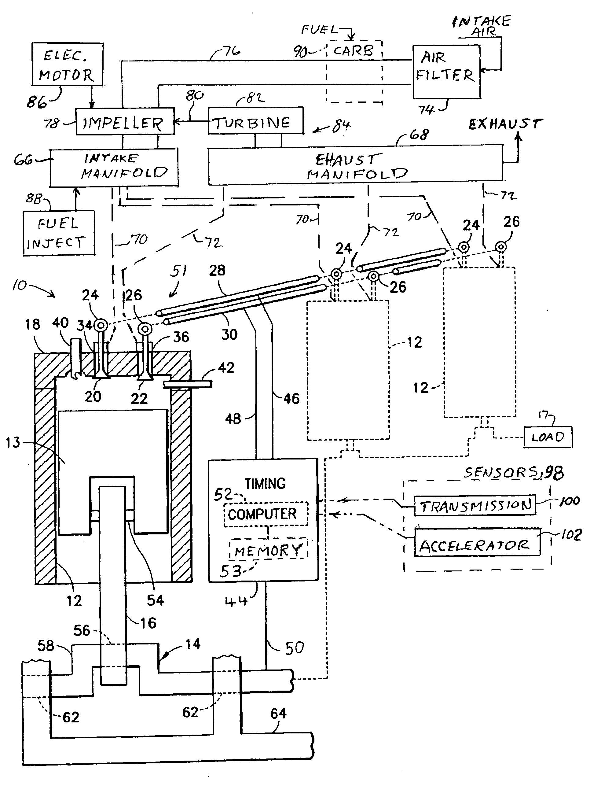
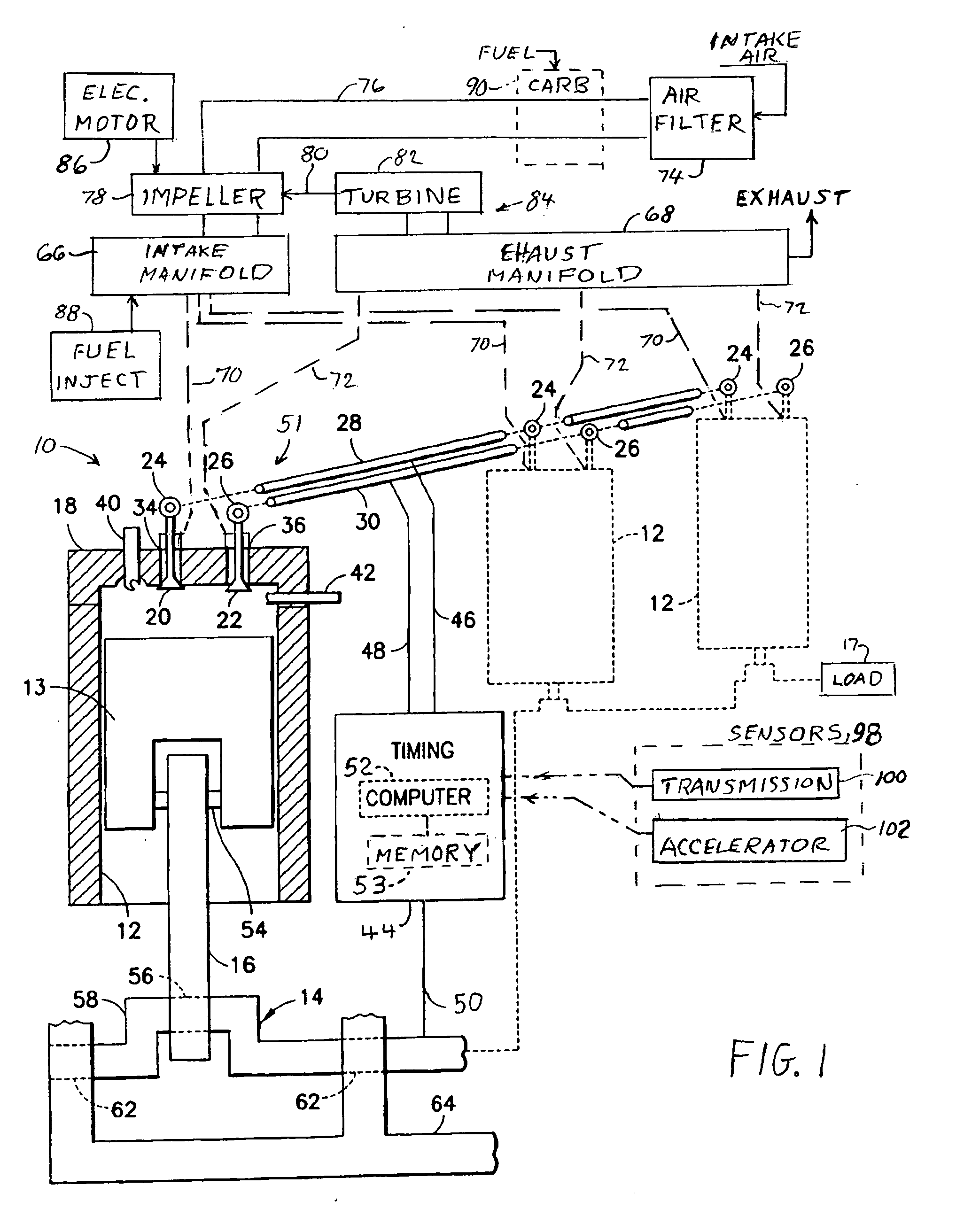
[0020]In the preferred embodiment of the invention, the valves are driven by a camshaft assembly wherein, for each cylinder, a single camshaft drives both of the exhaust and the intake valves or, alternatively, separate camshafts are provided for each of the exhaust and the intake valves. The valves, in cooperation with the camshaft assembly, constitute a valve assembly operable with a computer, which is responsive to engine and vehicular driving parameters, to enable operation of the engine in an automatic mode wherein the closing times of an intake valve are selectable automatically in response to vehicular driving conditions. Since, in a two stroke engine the camshaft rotates at the same speed as the crankshaft, the cams can be part of the crankshaft, if desired, eliminating the need for a separate camshaft. The crankcase, which serves for holding the lubricating oil, encircles the crankcase and is attached to the engine block opposite the cylinder head.
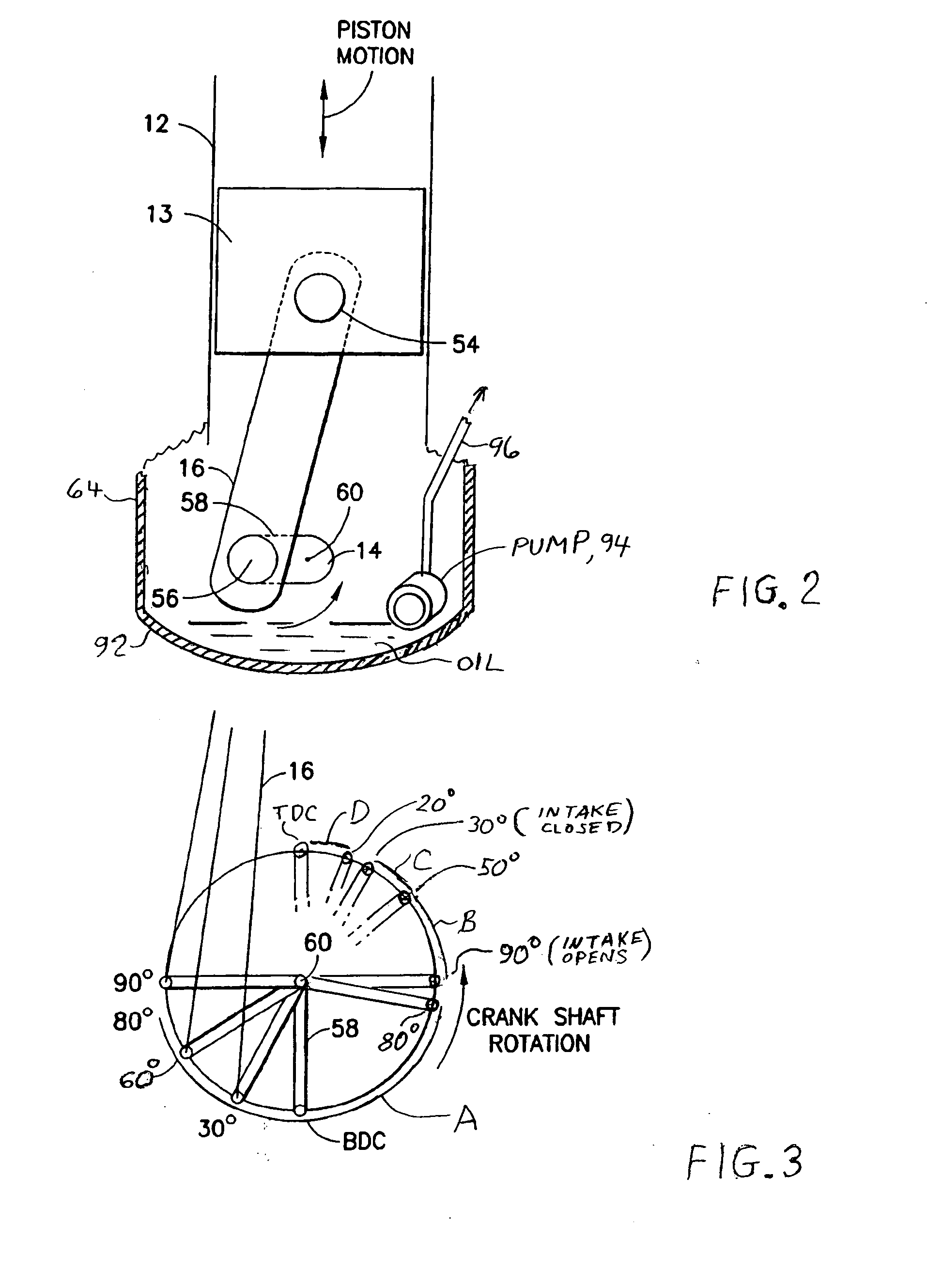
[0021]A complete cycle in the operation of a cylinder occurs within a single revolution of the crankshaft, and includes: (1) ignition of the fuel-air mixture at a terminal stage of the upstroke, (2) the burning of fuel for driving the piston in the initial stage of the downstroke, (3) the exhausting of the products of combustion during the final stage of the downstroke and may continue into the initial stage of the upstroke, and (4) the introduction of the fuel-air mixture with a following relatively small amount of compression of the fuel-air mixture at a middle stage following the closing of the exhaust valve and prior to the terminal stage of the upstroke. It is noted that, at the terminal phase of the upstroke, the piston is located very close to the cylinder head, and continued rotation of the crankshaft produces relatively little movement of the piston. Therefore, the conclusion of the induction of fuel (which, in the preferred embodiment is a vaporous mixture of fuel and air) concurrently with the location of the piston being very close to the cylinder head insures a minimization of any compression of the fuel-air mixture prior to ignition of the fuel.

Problems solved by technology

But it does not reach it's full potential because it has to overcome the greater compression ratio.
There is a practice in the construction of the four-stroke gasoline engine (as used in automobiles) of keeping the intake valve open, during the induction stroke, past bottom dead center, this resulting in a small decrease in the compression of the compression stroke.
By way of example, even in an idling engine, there is significant wasting of energy.
It is believed that engine tasks, such as the compressing of a fuel-air mixture in the compression stroke, and the sucking in of fuel-air mixture during the induction stroke require energy from the fuel, and are a source of wastage of fuel if these tasks consume more energy than is necessary for the driving of the vehicle.
It is noted also that the simplified mechanical design, generally employed in the two-stroke engine, while introducing reliability due to the mechanical simplicity of the engine, suffers from the disadvantage of noxious engine emissions associated with the addition of engine lubricant to the fuel.
It is necessary to add engine lubricant to the gasoline because the intake and exhaust ports in the cylinder walls do not allow for the use of a lubricating-oil crankcase and its associated oil pump to keep the engine components lubricated properly.
For an octane fuel, the resulting temperature rise, from the compression, is not enough to produce ignition or the air-fuel mixture.
However, in experiments by the present inventor, it has been observed that an intake fuel-air mixture employing heating oil or diesel fuel is subject to ignition before the piston reaches top dead center.

Method used


Image

  • Two-stroke internal combustion engine with valves for improved fuel efficiency
  • Two-stroke internal combustion engine with valves for improved fuel efficiency
  • Two-stroke internal combustion engine with valves for improved fuel efficiency

Examples


Embodiment Construction

[0032]With respect to both four-stroke and two-stroke engines, it is useful for appreciating the present invention in the two-stroke engine to review the effect of constructing pistons of different length, so as to understand the effect of using a taller piston in providing a higher expansion ratio in a given cylinder than is obtained with the use of a shorter piston. By way of example in the construction of a piston within its cylinder, in the case of a gasoline engine operating with the four-stroke process, when the piston in the cylinder is at top dead center (TDC), there is 1 cm (centimeter) between the top surface of the piston and the cylinder head. If the length of a stroke is 7 cm, then at bottom dead center (BDC) there is 8 cm from the top of the piston head to the cylinder head, this resulting in a compression stroke with 8:1 compression ratio and a power stroke expansion ratio of 8:1. The diesel engine four-stroke cycle differs from this pattern only by having a higher co...


PUM


Abstract

A two-stroke cycle internal combustion engine has a cylinder with a cylinder head closing off an end of the cylinder, a crankshaft and a piston connecting with the crankshaft to move the piston in a reciprocating movement within the cylinder. Intake and exhaust valves move into and out of a combustion chamber for openings and closures of the valves. A mixture of fuel and air is forced into the cylinder during an open interval of the intake valve beginning in the middle of the upstroke and terminating in a range of 20-60 degrees before top dead center to improve efficiency and choice of fuel by minimizing compressive forces of the piston during the upstroke. Timing of the closure of the intake valve may be delayed automatically with a reduction in crankshaft angular speed.

Description

FIELD OF THE INVENTION[0001]This invention relates to a two-stroke internal combustion engine with an oil pump and crankcase, and intake and exhaust valves and force-fed intake fuel-air mixture for improved fuel efficiency.BACKGROUND OF THE INVENTION[0002]Internal combustion engines have been constructed in the forms of two-stroke and four-stroke engines. In both forms of the engine, the engine employs one or more cylinders, each cylinder having a piston movable therein with reciprocating motion for the driving of a crankshaft of the engine. Output power of the engine, for the driving of a load, is obtained from the rotating crankshaft. A cylinder head closes off one end of each of the cylinders, opposite the crankshaft. In each of the pistons, the piston connects via a connecting rod to an arm of the crankshaft for conversion between the reciprocating motion of the piston and the rotational motion of the crankshaft. A combustion chamber is defined within each cylinder in the space ...

Claims


Application Information

Patent Timeline
Patent Type & Authority Applications(United States)
IPC IPC(8): F02B25/18
CPCF01L1/047F01L1/0532F01L1/38F01L2001/0535Y02T10/142F02B37/00F02B2075/025F02B2275/32F02B25/145Y02T10/12
Inventor ROBINSON, BARNETT JOEL
Owner ROBINSON BARNETT JOEL
Learn More