Apparatus and method for high temperature drilling operations

a technology of stators and rotors, applied in the direction of machines/engines, liquid fuel engines, borehole/well accessories, etc., can solve the problems of accelerated rotor and stator wear, stalling, and certain output limitations of rotor and stator assemblies, and achieve high mechanical loading

Inactive Publication Date: 2010-02-18
HALLIBURTON ENERGY SERVICES INC
View PDF12 Cites 100 Cited by
  • Summary
  • Abstract
  • Description
  • Claims
  • Application Information

AI Technical Summary

Benefits of technology

[0010]The present invention disclosed herein is directed to an improved rotor and stator assembly for use in downhole drilling systems to convert the hydraulic energy of a circulating fluid to the mechanical energy of a rotating shaft to turn a drill bit. The rotor and stator assembly of the present invention is capable of withstanding high mechanical loading and displays no incompatibility with circulating fluids. In addition, the rotor and stator assembly of the present invention can be operated at the elevated temperatures experienced during the drilling of a wellbore that traverses subterranean hydrocarbon bearing formations.

Problems solved by technology

It has been found, however, that typical rotor and stator assemblies have certain output limitations.
For example, operations above a maximum differential pressure may cause fluid leakage between the rotor and stator seals which may result in no rotation of the bit due to the rotor becoming stationary or stalling in the stator.
Likewise, operations above a maximum torque production value may result in accelerated rotor and stator wear as well as stalling.
It has been found, however, that conventional power sections commonly fail due to failure of the elastomeric element of the stator.
For example, these failures may occur due to high mechanical loading, elastomer fatigue or incompatibility of the circulating fluid and the elastomer.
In addition, high temperature affects commonly result in the failure of the elastomeric element.
Excessive temperatures may result from the high downhole temperature as well as hysteresis heat buildup caused by repeated flexing of the elastomer by the rotor.
This heat buildup may be exacerbated by expansion of the elastomer, which increases the compressive interference between the rotor and the stator.
This heat buildup not only reduces the life cycle of the elastomer but may also lead to a failure in the bond between the elastomer and the metal surface of the stator housing.

Method used


Image

  • Apparatus and method for high temperature drilling operations
  • Apparatus and method for high temperature drilling operations
  • Apparatus and method for high temperature drilling operations

Examples


Embodiment Construction

[0027]While the making and using of various embodiments of the present invention are discussed in detail below, it should be appreciated that the present invention provides many applicable inventive concepts, which can be embodied in a wide variety of specific contexts. The specific embodiments discussed herein are merely illustrative of specific ways to make and use the invention, and do not delimit the scope of the invention.

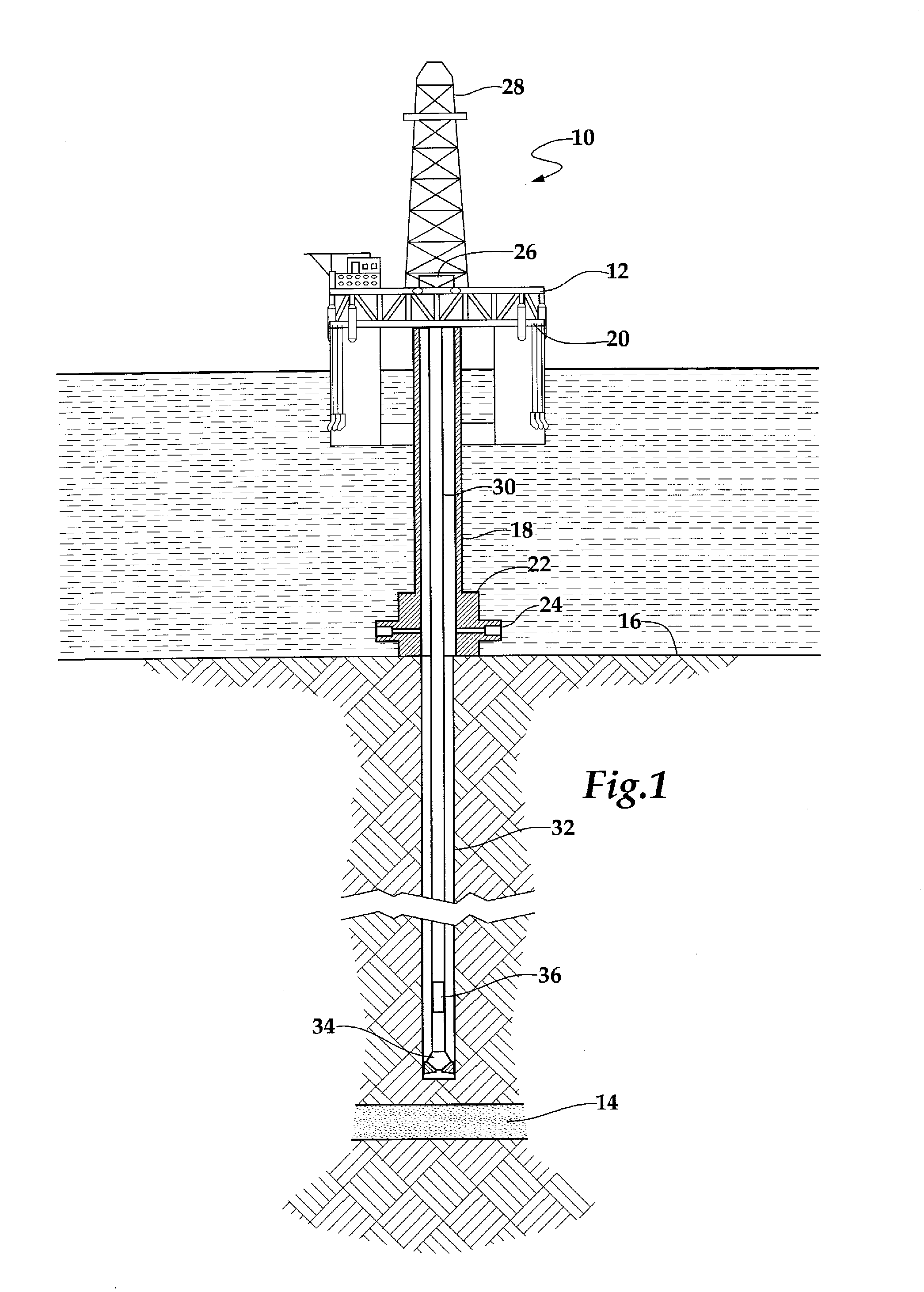
[0028]Referring initially to FIG. 1, an offshore oil and gas production platform operating an apparatus for drilling a wellbore according to the present invention is schematically illustrated and generally designated 10. A semi-submersible platform 12 is centered over a submerged oil and gas formation 14 located below sea floor 16. A semi-submersible platform 12 is centered over a submerged oil and gas formation 14 located below sea floor 16. A subsea conduit 18 extends from deck 20 of platform 12 to wellhead installation 22 including blowout preventers 24. Pl...


PUM


Abstract

An apparatus (50) for drilling a wellbore that transverses a subterranean hydrocarbon bearing formation. The apparatus (50) includes a drill string (52) having an inner fluid passageway (66). A drill bit (64) is disposed at a distal end of the drill string (52) and is operable to rotate relative to at least a portion of the drill string (52). A fluid motor (54) is disposed within the drill string (52) and is operable to rotate the drill bit (64) in response to a circulating fluid received via the inner fluid passageway (66) of the drill string (52). The fluid motor (54) has a stator (68) with (n) lobes and a rotor (70) with (n−1) lobes. The stator (68) includes an inner surface formed from a first material and the rotor (70) includes an outer surface formed from a second material that is dissimilar to the first material.

Description

CROSS-REFERENCE TO RELATED PATENT APPLICATIONS[0001]This is a continuation-in-part application of copending application Ser. No. 12 / 002,710, filed on Dec. 18, 2007.TECHNICAL FIELD OF THE INVENTION[0002]This invention relates, in general, to rotor and stator assemblies for use in fluid motors and progressive cavity pumps and, in particular, to an improved rotor and stator assembly for use in high temperature operations.BACKGROUND OF THE INVENTION[0003]Without limiting the scope of the present invention, its background will be described with reference to stator and rotor assemblies of power sections of positive displacement fluid motors for use in downhole drilling operations, as an example.[0004]In a typical power section of a positive displacement fluid motor used in drilling a wellbore that traverses subterranean hydrocarbon bearing formations, power generation is based upon the Moineau pump principle. In this type of motor design, a stator and rotor assembly converts the hydraulic...

Claims


Application Information

Patent Timeline
Patent Type & Authority Applications(United States)
IPC IPC(8): E21B4/02E21B7/00F01C1/10
CPCE21B4/02E21B43/128F01C1/107F04C2240/603F04C13/008F04C2230/91F04C2/1071
Inventor SNYDER, JOHN K.GAWSKI, VICTORSLAY, JEREMY BUCRAY, THOMAS WAYNE
Owner HALLIBURTON ENERGY SERVICES INC
Why Eureka
Try Eureka