Driving Method for High Efficiency Mercury-Free Flat Light Source Structure, and Flat Light Source Apparatus

a flat light source and mercury-free technology, applied in the direction of static indicating devices, gaseous cathodes, instruments, etc., can solve the problems of reduced light efficiency, increased manufacturing cost, and difficulty in constructing an optimized flat light source apparatus with sufficient luminance and luminous efficiency, and achieve short time and enhanced luminous efficiency

Active Publication Date: 2010-02-18
SEOUL NAT UNIV R&DB FOUND
View PDF18 Cites 4 Cited by
  • Summary
  • Abstract
  • Description
  • Claims
  • Application Information

AI Technical Summary

Benefits of technology

[0021]Accordingly, it is an aspect of the present invention to provide a flat light source structure with enhanced luminous efficiency by inducing a stable discharge over the entire surface and by adjusting brightness in short time, and a driving method thereof.
[0022]It is another aspect of the present invention to provide a flat light source structure with a wide driving margin and a wide operational condition and a driving method thereof.
[0023]It is further another aspect of the present invention to provide a flat light source structure having high brightness and efficiency by optimizing the structure of the phosphor layer and the driving method thereof.

Problems solved by technology

However, there is a difficulty in constructing an optimized flat light source apparatus with sufficient luminance and luminous efficiency.
This kind of flat light source apparatuses are disadvantageous in that light efficiency decreases greatly and manufacturing cost becomes higher due to a lot of additional parts required for converting the line and / or point light source apparatuses to a flat light source apparatus.
Further, since the flat light source apparatus is implemented by assembling a plurality of light source apparatuses, it is difficult to partially emit light from selected areas or difficult to adjust their brightness.
However, a light source based on Mercury discharge is disadvantageous in that Mercury is expected to be restricted in use for lightings because it is classified as an environmentally hazardous material, and the light source becomes difficult to operate and its luminous efficiency decreases when the lamp temperature becomes low, which necessitates a Mercury-free discharge gas.
However, the conventional flat light source apparatus as shown in FIG. 3(e) has a disadvantage that the discharge contraction (filamentation) is easily caused.
In case that such a phenomenon appears, the brightness of the area where the discharge is concentrated abruptly enhances and a uniform brightness over the entire surface cannot be obtained.
Consequently, it can be regarded as a discharge mode change, and such a local discharge concentration is thought to be caused by the plasma instability.
The reasons thereof are diverse but the main reason is thought to be a non-uniform distribution of charged particles and thermal instability in the discharge space.
Repetition of the above procedures results in strong concentration of discharge along the line of electric force.
If the discharge mode changes due to the discharge contraction, the current abruptly increases and the discharge is contracted, and as a result, a uniform, whole surface discharge cannot be obtained.
Further, the conventional flat light source 100 shown in FIG. 1 is disadvantageous in that the phosphor layers adhere very weekly to the upper and lower substrate and can be easily separated from the surface of the substrates.

Method used


Image

  • Driving Method for High Efficiency Mercury-Free Flat Light Source Structure, and Flat Light Source Apparatus
  • Driving Method for High Efficiency Mercury-Free Flat Light Source Structure, and Flat Light Source Apparatus
  • Driving Method for High Efficiency Mercury-Free Flat Light Source Structure, and Flat Light Source Apparatus

Examples


Embodiment Construction

[0100]Reference will now be made in detail to the embodiments of the present invention, examples of which are illustrated in the accompanying drawings, wherein like reference numerals refer to like elements throughout. The embodiments are described below so as to explain the present invention by referring to the figures.

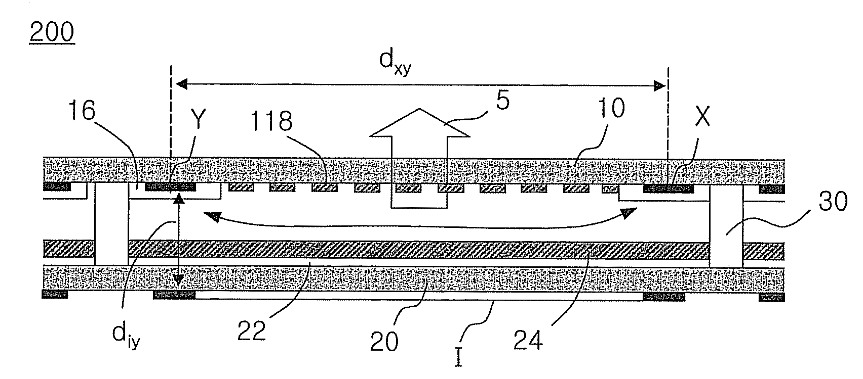
[0101]FIG. 4 is a sectional view schematically illustrating a flat light source structure according to the present invention. The flat light source structure 200 according to the present embodiment includes an upper substrate 10, a lower substrate 20, and a pair of main electrodes X and Y formed on the inner surface of the upper substrate 10, and further includes an auxiliary electrode I on the outer surface of the lower substrate 20 in order to obtain a uniform whole surface discharge over the entire area. The auxiliary electrode I includes a parallel component which is parallel to the main electrodes X and Y formed on the inner surface of an upper substrate 10, and...


PUM


Abstract

Disclosed are a new Mercury-free flat light source structure capable of enhancing and adjusting brightness, maintaining stable and uniform discharge, and improving luminous efficiency, and a large flat light source apparatus using the same Mercury-free flat light source structure as a unit cell capable of adjusting the brightness and causing local discharges in selected areas, and a driving method thereof.The flat light source structure according to the present invention includes an upper substrate made of a light transmitting material; a lower substrate separated from the upper substrate by a distance; a barrier rib for maintaining the distance, thereby defining a discharge space filled with a discharge gas with a predetermined pressure; a phosphor coated on at least one of the inner surfaces of the upper substrate and the lower substrate, respectively; a pair of main electrodes disposed at predetermined positions on the surface of the upper or lower substrate and applied with a predetermined driving voltage, frequency and duty ratio to excite the phosphor by plasma generated due to electric field induced in the discharge space; an auxiliary electrode formed at a predetermined position on the lower and / or upper substrate(s) to have a parallel component which is parallel with any one of the main electrodes when viewing the discharge space from the upper substrate and a perpendicular component which traverses the electrodes across the pair of main electrodes.

Description

CROSS-REFERENCE TO RELATED APPLICATIONS[0001]This application is a division of and claims priority to U.S. patent application Ser. No. 11 / 407,703 filed Apr. 20, 2006, the disclosure of which is incorporated herein by reference.[0002]This application claims priority from Korean Patent Applications No. 2005-32560 and No. 2006-33281, filed on Apr. 20, 2005 and Apr. 12, 2006, respectively, in the Korean Intellectual Property Office, and U.S. patent application Ser. No. 11 / 407,703, filed on Apr. 20, 2006, the disclosure of which is incorporated herein by reference.BACKGROUND OF INVENTION[0003]1. Field of Invention[0004]The present invention relates to a Mercury-free flat light source structure, and more particularly, to a Mercury-free flat light source structure capable of enhancing and adjusting brightness, maintaining stable and uniform discharge, and improving luminous efficiency, a large flat light source apparatus using the same Mercury-free flat light source structure as a unit cel...

Claims


Application Information

Patent Timeline
Patent Type & Authority Applications(United States)
IPC IPC(8): H05B41/00G09G3/28G09G3/293G09G3/294G09G3/298
CPCC09K11/595C09K11/7734C09K11/7797G09G3/2022G09G3/28H01J65/04G09G3/294G09G3/2983G09G3/2986H01J61/305H01J61/545G09G3/293
Inventor WHANG, KI-WOONGLEE, JU-KWANG
Owner SEOUL NAT UNIV R&DB FOUND
Why Eureka
Try Eureka