Rotation detector,wheel bearing equipped therewith and process for manufacturing the same

a technology of rotating detectors and wheel bearings, which is applied in the direction of magnetic sensor geometrical arrangements, instruments, mechanical apparatuses, etc., can solve the problems of inability to expect adhesion between the covering material and the component parts built therein, water proofing property problems, and the like, so as to improve durability, avoid damage to the sensor component parts, and improve water proofing ability

Inactive Publication Date: 2010-02-18
NTN CORP
View PDF16 Cites 12 Cited by
  • Summary
  • Abstract
  • Description
  • Claims
  • Application Information

AI Technical Summary

Benefits of technology

[0015]An object of the present invention is to provide a rotation detecting device, in which the difference in thermal expansion resulting from the self-heating of the sensor component parts and the environmental temperature can be absorbed, which has an excellent water proofing property, in which even when vibrations and / or external forces acts, damage to the sensor component parts can be avoided, allowing it to have an excellent durability, and in which the cost of manufacture can be reduced, and also to provide a wheel support bearing assembly equipped with such rotation detecting device and a method of manufacturing the rotation detecting device.

Problems solved by technology

(1) No adhesion between the covering material and the component parts built therein cannot be expected.
(2) As a result of change in ambient temperature and self-heating of electronic component parts built therein, a gap tends to occur between the covering material and the built-in component parts due to the difference in thermal expansion thereof, thus posing a problem in water proofing property.
(3) Even when an external force acts on the sensor unit molded and a plastic deformation occurs in the covering material, a gap tends to occur between the covering material and the built-in component parts, thus posing a problem in water proofing property.
(4) When an external force acts on the sensor unit molded, such force acts directly on the built-in component parts since the covering material comprised of a resinous material is less susceptible to deformation and, therefore, it will constitute a cause of breakage of the sensor unit.
(5) The covering material comprised of the resinous material lacks a vibration absorbing capability and, therefore, there is a problem in durability relative to external vibrations.
(6) With the molding by means of the conventional injection molding, a nozzle through which a molten resin flows, runners for leading the molten resin towards a cavity portion, which eventually forms a molded product, and inflow gates leading to the cavity portion are required. In order to smoothen the flow of the molten resin to thereby increase the yield, the appropriate number of pieces manufactured at one time is within the range of a few pieces to some tens pieces and thus, the number of pieces molded at one time is limited.
Also, the rotation detecting device such as, for example, the ABS sensor used as fitted to an automobile component part, particularly, the hub bearing assembly, is generally exposed to the road surface and is therefore wetted with a muddy salty water and is also placed under severe environment, in which a temperature change from some tens degree to minus some tens degree occurs.
Yet, since the rotation detecting device is positioned below the suspension system, it is considerably affected by vibrations induced during the travel of the automotive vehicle.
Any erroneous operation of the ABS sensor brings about a considerable influence on the vehicle traveling safety.
Those keen demands cannot be fulfilled with the rotation detecting device formed by the conventional resin molding.

Method used


Image

  • Rotation detector,wheel bearing equipped therewith and process for manufacturing the same
  • Rotation detector,wheel bearing equipped therewith and process for manufacturing the same
  • Rotation detector,wheel bearing equipped therewith and process for manufacturing the same

Examples


first embodiment

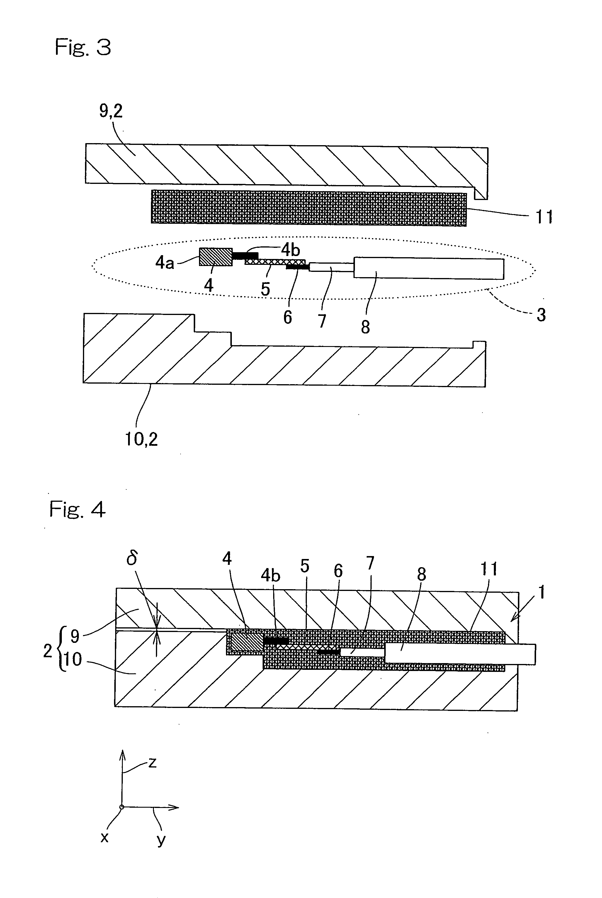
[0092]In the first embodiment described above, the upper mold 9 and the lower mold 10 are so structured as to form a predetermined minute gap δ between the upper mold 9 and the lower mold 10 in a condition in which the pressure is applied to a predetermined object to be pressed. By so designing, at the state in which the pressure is applied to the sensor assembly 3 forming an object to be pressed, it is possible to allow the excessive rubber material 11 to be discharged smoothly to the outside of the mold assembly 2. Accordingly, it is possible to avoid formation of shrinkage cavities inside the elastic member, which would otherwise result from the use of the rubber material 11 in a small quantity. It is possible to avoid such an inconvenience that if conversely the amount of the rubber material 11 is large, the rubber material 11 cannot be accommodated within the mold assembly 2 and the molding cannot therefore be accomplished satisfactorily.

[0093]According to the rotation detectin...

second embodiment

[0105]FIG. 5 illustrates a sectional view of the rotation detecting device according to the present invention. In FIG. 5, the fixing attachment 21 is made of a metallic material such as, for example, steel, aluminum, copper or brass, of a kind having an affinity to bond with the rubber material. In consideration of the corrosion resistance, the use of an austenitic stainless steel, a steel having been surface treated with zinc base alloy or an alumite treated aluminum is preferred. It is, however, to be noted that the metallic material that can be employed is not necessarily limited thereto. The fixing attachment 21 has a function of positioning the sensor 4 and the peripheral component parts. The fixing attachment 21 includes, mainly, a recessed portion 22 representing a concaved shape as viewed from side, a cable fixing portion 23 formed integrally with one side edge of the recessed portion 22 and a sensor fitting portion 24 formed integrally with the opposite side edge of the rec...

third embodiment

[0118]FIG. 7 is a sectional view showing the rotation detecting device according to the Referring to FIG. 7, the connecting member 25 has a rear end face fixed to the first wall area 22b at a lower portion thereof extending from a junction with one surface of the bottom area 22a to the supported cable insulating sheathes 7.

[0119]The connecting member 25 has a front end face, a lower half of which is fixed to the one surface portion of the second wall area 22c. The other surface portion of the second wall area 22c is exposed to the outside. A bottom face of the connecting member 25 is fixed to the one surface of the bottom area 22a of the recessed portion 22. The elastic member 11 A is fixed on one surface portion of the sensor fitting portion 24 and the opposite surface portion of the sensor fitting portion 24 is exposed to the outside. As described in connection with the second embodiment, the fixing attachment 21 serves to position the sensor 4 and the peripheral component parts ...


PUM

PropertyMeasurementUnit
elasticityaaaaaaaaaa
pressureaaaaaaaaaa
mechanical strengthaaaaaaaaaa

Abstract

A sensor assembly (3) is sandwiched together with a rubber material (11) mixed with a vulcanizing agent in a mold assembly (2) including an upper mold (9) and a lower mold (10). The upper and lower molds (9, 10), while completely sandwiching the sensor assembly (3), are heated for a predetermined length of time, and a pressure is then applied to the sensor assembly (3) to complete a compressive molding.

Description

CROSS-REFERENCE TO RELATED APPLICATIONS[0001]This application claims the benefit under 35 U.S.C. Section 371, of PCT International Application No. PCT / JP2007 / 001031, filed Sep. 21, 2007, which claimed priorities to Japanese Application Nos. 2006-256827, filed Sep. 22, 2006; Japanese Application No. 2006-262182, filed Sep. 27, 2006; Japanese Application No. 2006-262183, filed Sep. 27, 2006; Japanese Application No. 2006-262184, filed Sep. 27, 2006; Japanese Application No. 2006-262185, filed Sep. 27, 2006; Japanese Application No. 2006-262186, filed Sep. 27, 2006; Japanese Application No. 2006-262187, filed Sep. 27, 2006; Japanese Application No. 2006-281304, filed Oct. 16, 2006; Japanese Application No. 2007-223481, filed Aug. 30, 2007; the disclosures of all of which are hereby incorporated by reference.BACKGROUND OF THE INVENTION[0002]1. Field of the Invention[0003]The present invention relates to a rotation detecting device adapted to be employed in association with, for example,...

Claims


Application Information

Patent Timeline
Patent Type & Authority Applications(United States)
IPC IPC(8): F16C19/18G01B7/30H05K13/00
CPCG01R33/0005G01R33/0047G01R33/0052Y10T29/49002G01B7/30G01R1/04F16C41/007G01R33/07
Inventor OZAKI, TAKAYOSHIISHIKAWA, TOMOMITAKAHASHI, TORU
Owner NTN CORP
Why Eureka
Try Eureka