Negative Electrode for Hybrid Energy Storage Device

a technology of energy storage device and negative electrode, which is applied in the direction of electrolytic capacitor, cell component details, cell components, etc., can solve the problems that the equipment commonly used in the manufacture of conventional lead-acid batteries, motive power, stationary, etc., cannot be employed in the production of hybrid energy storage devices, and achieves good contact resistance properties and eliminates the need for high stack pressure

Inactive Publication Date: 2010-02-18
WAINWRIGHT D WALKER
View PDF57 Cites 39 Cited by
  • Summary
  • Abstract
  • Description
  • Claims
  • Application Information

AI Technical Summary

Benefits of technology

[0009]An advantage of the present invention is that an active material of the negative electrode is laminated onto an expanded graphite material, thereby eliminating the need for high stack pressure and achieving good contact resistance properties.
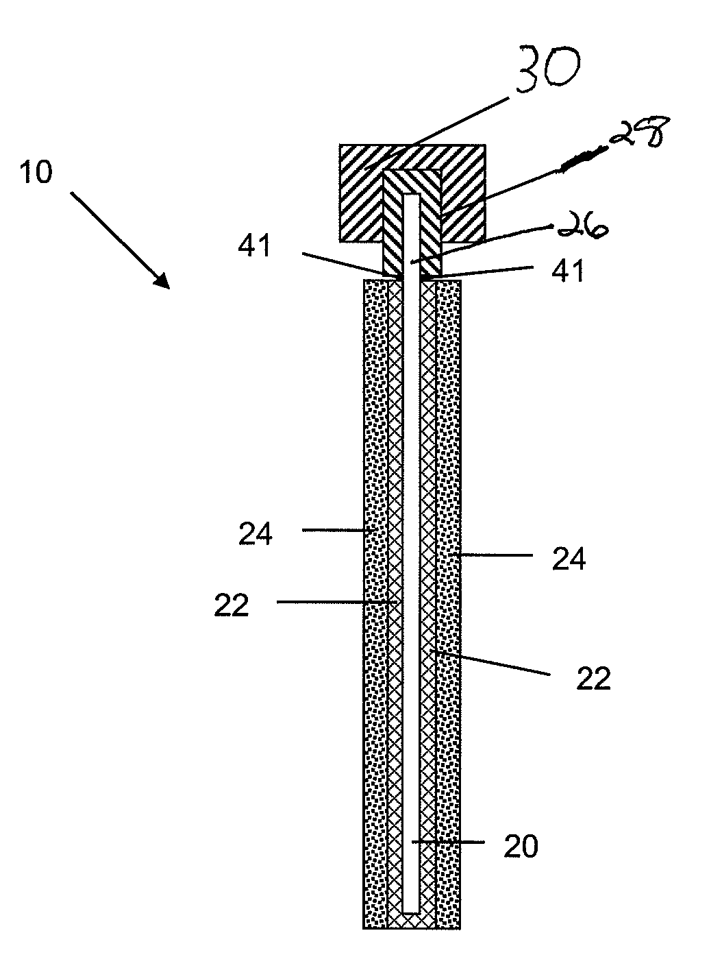
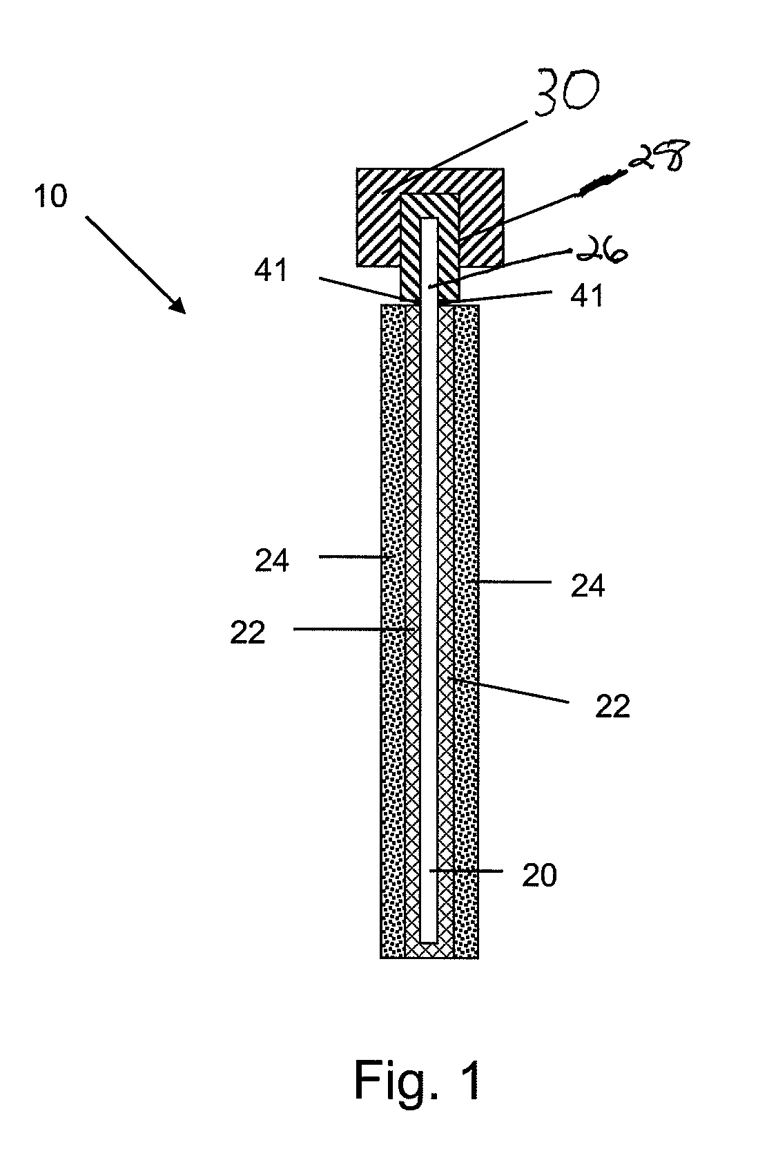
[0010]The above objects and advantages are satisfied by a negative electrode for a hybrid energy storage device comprising a current collector; a corrosion-resistant conductive coating secured to at least one face of the current collector; and a sheet comprising activated carbon adhered to and in electrical contact with the corrosion-resistant conductive coating. A tab portion extends from a side of the current collector. A lug comprising a lead or lead alloy encapsulates at least part of the tab portion.
[0011]As used herein “substantially”, “generally”, “relatively”, “approximately”, and “about” are relative modifiers intended to indicate permissible variation from the characteristic so modified. It is not intended to be limited to the absolute value or characteristic which it modifies but rather approaching or approximating such a physical or functional characteristic.
[0012]References to “one embodiment”, “an embodiment”, or “in embodiments” mean that the feature being referred to is included in at least one embodiment of the invention. Moreover, separate references to “one embodiment”, “an embodiment”, or “in embodiments” do not necessarily refer to the same embodiment; however, neither are such embodiments mutually exclusive, unless so stated, and except as will be readily apparent to those skilled in the art. Thus, the invention can include any variety of combinations and / or integrations of the embodiments described herein.
[0013]In the following description, reference is made to the accompanying drawings, which are shown by way of illustration to specific embodiments in which the invention may be practiced. The following illustrated embodiments are described in sufficient detail to enable those skilled in the art to practice the invention. It is to be understood that other embodiments may be utilized and that structural changes based on presently known structural and / or functional equivalents may be made without departing from the scope of the invention.

Problems solved by technology

It is also conventional wisdom that equipment generally used to manufacture conventional lead-acid batteries and commonly employed in the automotive industry, motive power, stationary, and other energy storage applications cannot be employed in the production of hybrid energy storage devices.

Method used


Image

  • Negative Electrode for Hybrid Energy Storage Device
  • Negative Electrode for Hybrid Energy Storage Device
  • Negative Electrode for Hybrid Energy Storage Device

Examples


example 1

Impregnated Graphite Corrosion-Resistant Coating

[0044]Nine negative electrodes were made without an active material, but with 3 different types of graphite foil (grafoil). Indicating paper was cut to fit (wrap around) on both sides of a copper current collector. Four electrodes were made using an automated glue machine and 5 electrodes were made with the same glue but applied by hand, so that if there are leaks from the glue it could be determined whether there is a faulty glue process or a failure of the glue.

[0045]All electrodes were saturated with sulfuric acid, squeezed tightly into a battery case, and then pressurized at 35 psi for 30 minutes. After depressurizing, the electrodes were carefully rinsed and the grafoil was peeled away from the copper current collector to look for signs of leaking.

[0046]The 3 electrodes made of grafoil with 100% paraffin wax impregnation always leaked in the center indicating failure of the grafoil not the glue, as shown in FIG. 3. The 3 electrode...

example 2

Lead Lug on Tab Portion

[0047]A lead-tin coating was used to protect a copper tab from corrosion, as illustrated in FIG. 7A. The lead-tin material corrodes and forms a corrosion resistance layer of lead sulfate. However, a cast on strapping process results in a significant depletion of the coating. During the COS operation, the tab is placed in contact with molten lead. The heated lead causes significant heating of the tab resulting in the melting of the protective lead-tin coating which is drawn into the lead strap, leaving the copper tab with a very thin protective coating. As a result, the copper tab corroded from a sulfuric acid electrolyte, as shown in FIG. 6.

[0048]A lead lug was molded onto a copper tab in place of a lead-tin coating, as illustrated in FIG. 7B. The lead lug did not melt during a COS operation and thus maintained a protective coating.


PUM

PropertyMeasurementUnit
conductivityaaaaaaaaaa
densityaaaaaaaaaa
thicknessaaaaaaaaaa

Abstract

A negative electrode for a hybrid energy storage device includes a current collector; a corrosion-resistant conductive coating secured to at least one face of the current collector; a sheet comprising activated carbon adhered to the corrosion-resistant conductive coating; a tab portion extending from a side of the negative electrode; and a lug comprising a lead or lead alloy that encapsulates at least part of the tab portion.

Description

[0001]This PCT international application claims priority of U.S. provisional application Ser. No. 60 / 853,439 filed on 23 Oct. 2006.FIELD OF INVENTION [0002]The present invention relates to a negative electrode for a hybrid energy storage device.BACKGROUND OF INVENTION[0003]Hybrid energy storage devices, also known as asymmetric supercapacitors or hybrid battery / supercapacitors, combine battery electrodes and supercapacitor electrodes to produce devices having a unique set of characteristics including cycle life, power density, energy capacity, fast recharge capability, and a wide range of temperature operability. Hybrid lead-carbon energy storage devices employ lead-acid battery positive electrodes and supercapacitor negative electrodes. See, for example, U.S. Pat. Nos. 6,466,429; 6,628,504; 6,706,079; 7,006,346; and 7,110,242.[0004]The conventional wisdom is that any new battery or supercapacitor technology assembles components and uses techniques that are unique to that technology...

Claims


Application Information

Patent Timeline
Patent Type & Authority Applications(United States)
IPC IPC(8): H01M4/02H01M50/541
CPCH01G9/04H01G9/155H01G11/04H01G11/12H01G11/28Y10T29/417H01G11/46H01G11/76H01G11/26H01G11/32Y02E60/13H01G11/38H01G11/68H01G11/70H01G11/22H01G11/34H01G11/74
Inventor BUIEL, EDWARDESHKENAZI, VICTORRABINOVICH, LEONIDSUN, WEIVICHNYAKOV, VLADIMIRSWIECKI, ADAMCOLE, JOSEPH
Owner WAINWRIGHT D WALKER
Why Eureka
Try Eureka