
Connecting device and method for manufacturing the same

a technology of connecting devices and manufacturing methods, applied in the manufacture of contact members, external electrodes, electrotherapy, etc., can solve the problems of increased cost, two components will become misaligned, and expensive manufacturing, so as to improve the impedance of the helix surface, improve the shape and facilitate the modification of the helix winding

Inactive Publication Date: 2010-02-18
ST JUDE MEDICAL
View PDF4 Cites 2 Cited by
  • Summary
  • Abstract
  • Description
  • Claims
  • Application Information

AI Technical Summary

Benefits of technology

[0010]An object of the invention is to reduce the disadvantages with prior art connecting devices. More precisely it is an object of the invention to facilitate and reduce costs for manufacture of the connecting device as well as facilitate assembling of the medical implantable lead.
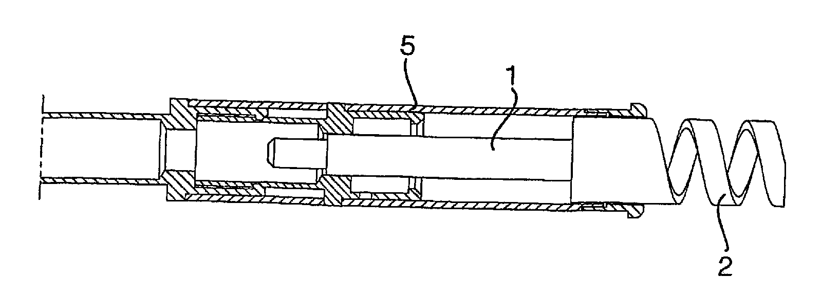
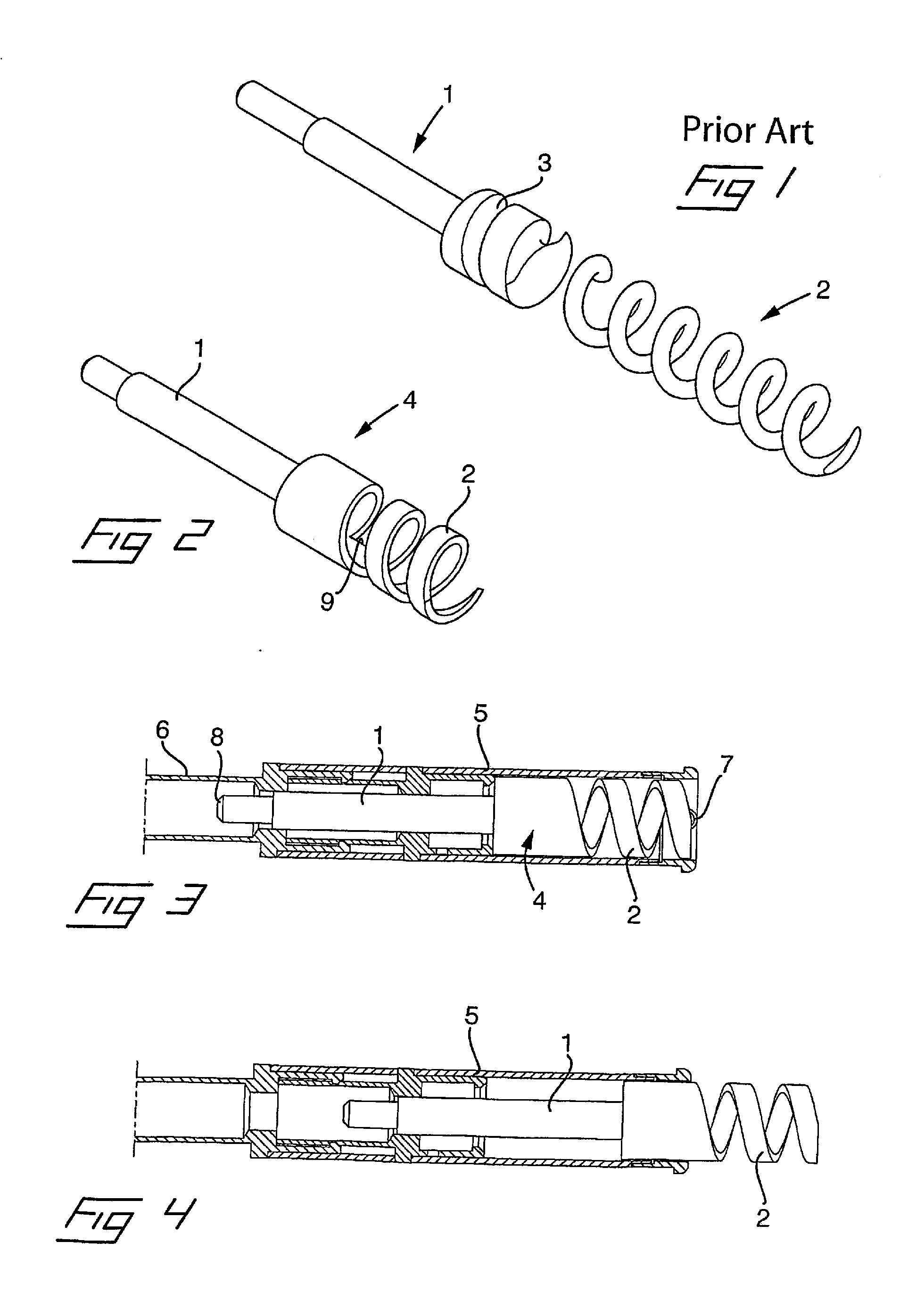
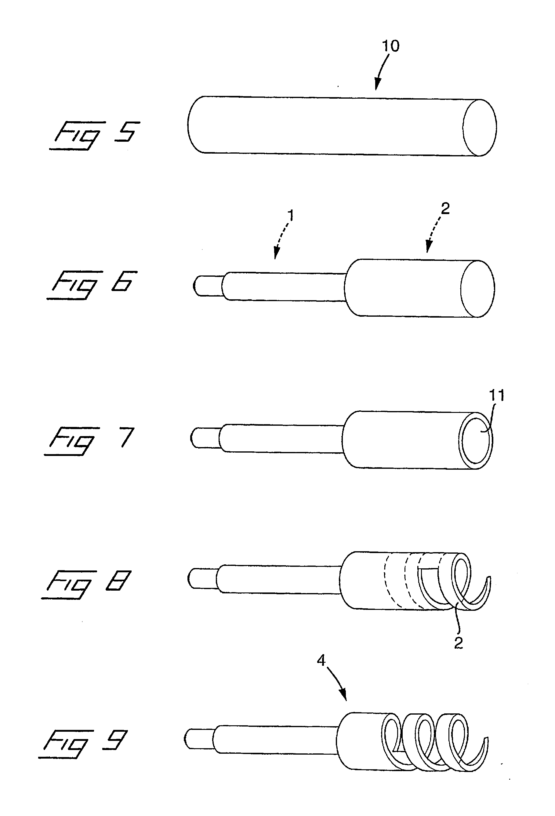
[0012]The invention is based on the recognition that the above object may be achieved by making the connecting device in one piece, i.e. the helix and the shaft being integrated and manufactured in the same manufacturing process. In this way it is possible to completely eliminate any misalignment problems between the shaft and the helix. The complexity of the manufacture will also be reduced since any attachment area between the shaft and the helix can be dispensed with as well as the assembly process. Moreover, there is no risk of insufficient mechanical or electrical contact between the helix and the shaft.
[0014]One advantage with forming the helix windings by a material removing process, is that the form of the helix easily can be altered according to special desires or requirements. For example, the helix can be made with a variable cross section over its length, with projections or the like. On the whole, the invention makes it easier to perform modifications of the shape of the helix windings since it will be only one component that has to be altered instead of at least two in case of a prior art connecting device, assembled from a separate shaft and helix, in which also the mating part of the shaft has to be altered.
[0015]Sometimes it is desirable to improve and / or adjust the impedance of the helix surface by coating at least some portions of the surface with an electrical insulating material. By means of the material removing process according to the invention, this selective coating can be facilitated. E.g. when forming the helix of an electrically conducting material, the outer surface of the blank as well as, if desirable, also the inner surface of the bore, can easily be coated with an electrically insulating material, such that when the helix windings are formed by a material removing process, the cut edge surfaces of the helix windings will be electrically conductive. On the other hand, when forming the helix of an electrically insulating material, the outer surface of the blank as well as, if desirable, also the inner surface of the bore, can easily be coated with an electrically conducting material, such that when the helix windings are formed by a material removing process, the cut edge surfaces of the helix winding will be electrically insulated.

Problems solved by technology

However, there are several disadvantages associated with prior art connecting devices of the above designated kind.
The connecting devices used today are composed of at least two components, i.e. a shaft and a helix, that needs to be aligned with each other within tight tolerances and both are complex and expensive to manufacture and a separate assembling process is necessary to accomplish the assembling.
In the assembling process of the shaft and the helix it is always a risk that the two components will become misaligned, which is a common reason for rejection with increased costs as a consequence.
It is also a risk for poor mechanical and / or electrical contact between the helix and the shaft when assembling them together.

Method used


Image

  • Connecting device and method for manufacturing the same
  • Connecting device and method for manufacturing the same
  • Connecting device and method for manufacturing the same

Examples


Embodiment Construction

[0021]Reference is first made to FIG. 1, in which an embodiment of a prior art connecting device is shown. From the perspective view in FIG. 1 is seen that the connecting device is assembled of a shaft 1 and a helix 2 in form of separate components, wherein the helix is attached to the shaft by way of the most proximal turns of the helix mating and being in engagement with helical grooves 3 being formed in the distal end of the shaft. This has to effect that the shaft and the helix has to be manufactured in separate manufacturing processes and then being assembled into one unit under consideration of proper alignment of and electrical contact between the shaft and the helix in relation to each other. This necessitates a separate attachment process, such as welding, and suitable adaptation measures, such as forming of the grooves 3, to make the shaft and helix fit together.

[0022]Now reference is made to FIG. 2 of the drawings, in which an embodiment of a connecting device according t...


PUM

PropertyMeasurementUnit
lengthaaaaaaaaaa
shapeaaaaaaaaaa
distanceaaaaaaaaaa

Abstract

A connecting device for connection of a medical implantable lead to tissue inside a body has a helix adapted to be screwed out from a header sleeve at a distal end of the lead and into the tissue, and a shaft which carries the helix and is rotatably journalled in the lead and at the same time is displaceable to extend the helix into the tissue. The helix and the shaft are integrated and manufactured in one unitary piece. A method for manufacturing of such a connecting device includes the step of manufacturing the helix and shaft in one unitary piece.

Description

BACKGROUND OF THE INVENTION[0001]1. Field of the Invention[0002]The present invention relates to a connecting device for connection of a medical implantable lead to tissue inside a body, of the type having a helix adapted to be screwed out from a header sleeve at a distal end of the lead and into the tissue, and a shaft which carries the helix and is rotatably journalled in the lead and at the same time displaceable to extend the helix into the tissue.[0003]The invention also relates to a method for manufacturing such a connecting device.[0004]2. Description of the Prior Art[0005]For controlling and / or monitoring of an arbitrary organ inside a human or animal body, e.g. a heart by means of a pacemaker, it is common practice to attach an electrical lead to the organ for transmitting and receiving electrical signals to or from the organ. A common way to accomplish the attachment of the lead to the tissue, is to screw out a helix from a so called header sleeve at a distal end of the le...

Claims


Application Information

Patent Timeline
Patent Type & Authority Applications(United States)
IPC IPC(8): A61N1/05H01R43/00
CPCY10T29/49204A61N1/0573
Inventor JARL, PERHILL, ROLF
Owner ST JUDE MEDICAL
Learn More