
Method and apparatus for stenting

a stent and stent technology, applied in the field of implantable medical devices, can solve the problems of inflammation in the region, occlusion of the lumen, total blockage of the lumen, undesired narrowing of the lumen, etc., to achieve the effect of preventing restenosis, promoting a more favorable flow regime, and minimizing or eliminating any flow separation areas

Inactive Publication Date: 2010-02-18
MEDINOL LTD
View PDF35 Cites 20 Cited by
  • Summary
  • Abstract
  • Description
  • Claims
  • Application Information

AI Technical Summary

Benefits of technology

[0011]Accordingly, the present invention provides stent configurations that induce a more favorable flow regime (e.g., one that minimizes or eliminates flow disturbance in the treatment area) are provided. Specifically, a method and apparatus is disclosed which enables a physician to tailor the flow characteristics of the post-treatment site to avoid flow disturbances, or otherwise enhance aspects of fluid flow through the post-treatment site to avoid inflammatory effects.
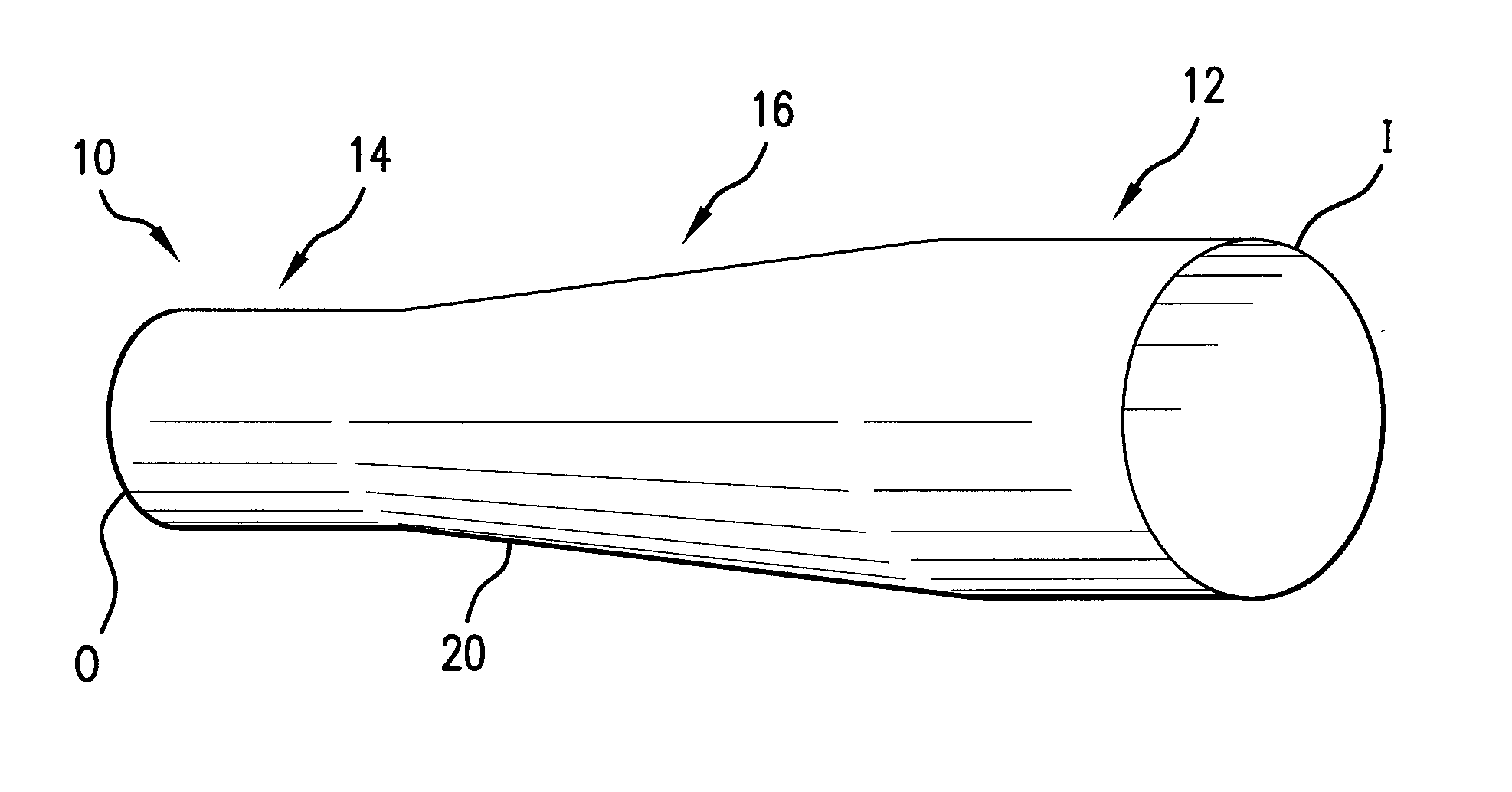
[0012]Embodiments of the present invention utilize a shaped, e.g., tapered, stent such that the flow pattern, as it relates to the probability of restenosis, is optimized relative to that which would be induced by a stent that was either non-tapered or tapered in such a way as to merely minimize the mechanical stress imposed on the wall.
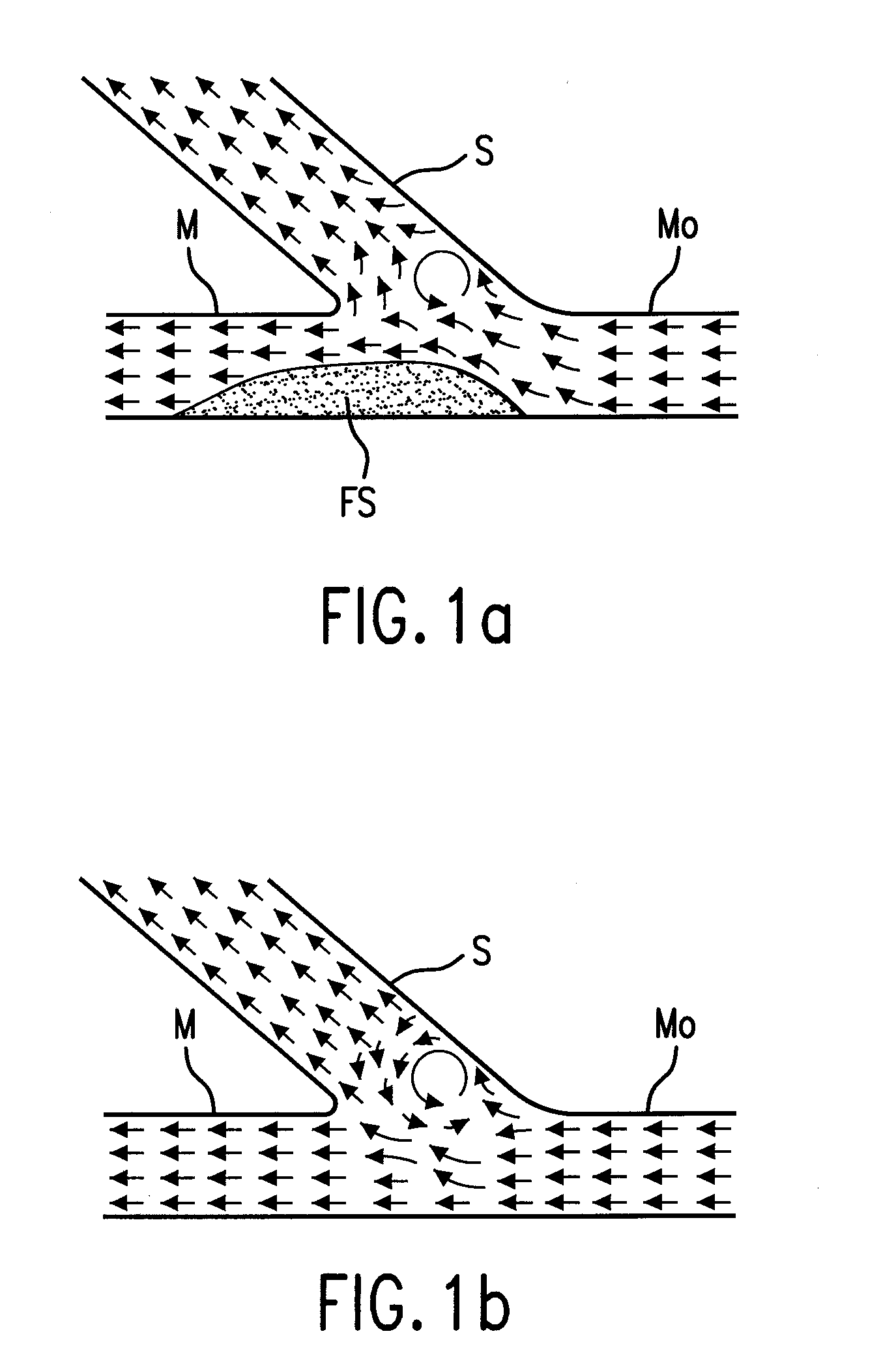
[0023]1. Include a region of flow disturbance (most commonly flow separation); the most common examples of this would be bifurcations. This region of flow disturbance which exists after stenting with present devices predisposes the stent to re-occlusion for any one of the factors mentioned above. Hence, reduction / elimination of the region of disturbance minimizes the probability of re-occlusion.
[0024]2. May not include a region of flow disturbance; the most common examples of this would be straight, tapered / non-tapered, non-bifurcated vessel segments. The stent is still predisposed to re-occlusion (as all stents are) due to a multitude of factors including vessel wall injury, inflammatory response, foreign body reaction etc, but the introduction of an artificial geometry in these cases alters the flow pattern in such a way as to offset non flow-disturbance related factors with the end result being a minimization of the probability of restenosis.
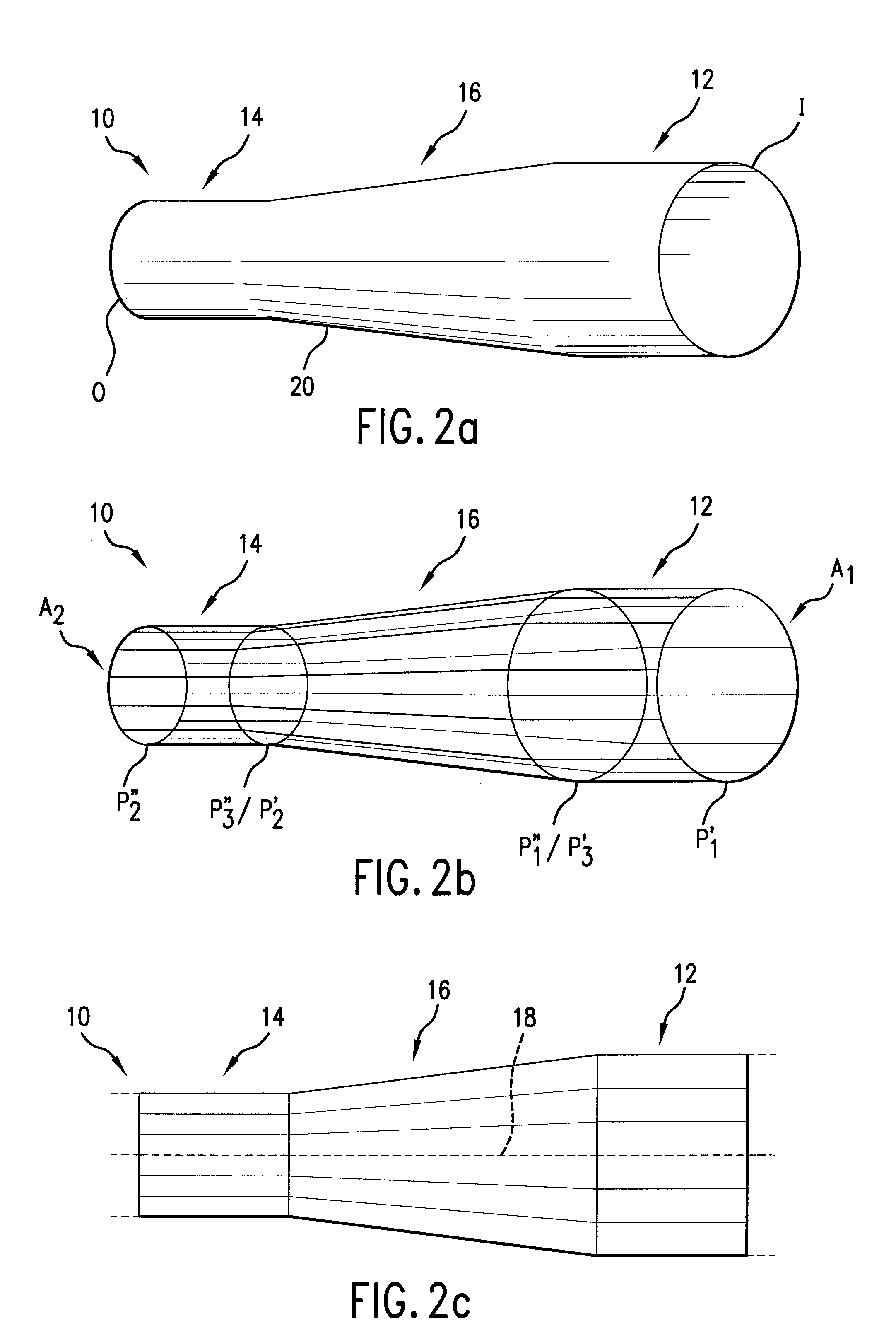
[0026]The shape of the stent may be specifically designed to improve the flow regime, e.g., by minimizing any flow disturbance, and the resultant narrowing of the lumen. This may be accomplished with a self-expanding stent that has, for example, at least two sections with different cross-sectional areas, and a tapered section connecting the two sections with different cross-sectional areas to one another. Of course these sections will have different cross-sectional areas.
[0029]Thus, these embodiments provide a method and apparatus for reshaping a lumen to promote more favorable flow regime, e.g., laminar flow, and minimize or eliminate any areas of flow separation, especially in areas that were traumatized by the angioplasty procedure in order to prevent restenosis. In general terms, this is done using stents that are configured to minimize flow disturbance. In the illustrated embodiments, these stents are configured so that they have a taper which alters the flow characteristics of the lumen.

Problems solved by technology

When a lumen is subjected to injury, white blood cells and other substances tend to converge on the injured region of the lumen bringing about inflammatory effects at that region.
These inflammatory effects tend to result in an occlusion of the lumen, that is, an undesired narrowing of the lumen or a total blockage of the lumen.
Moreover, in the lumen, there may be areas with flow disturbances.
These flow disturbances include areas of “flow separation,” in which vortices are created next to the vessel wall, rendering the blood essentially stagnant at those locations.
Such areas of flow separation are a particular problem in bifurcated lesions.
However, even lumens with a substantially constant diameter may have areas with undesirable flow separation or other flow disturbances.
That, in turn, may increase the probability that such white cells will penetrate the wall and will initiate an inflammatory effect, which can result in an undesirable narrowing of the lumen.
Finally, flow disturbance may cause or exacerbate vascular injury by promoting particle sedimentation and by inhibiting proper transport of waste materials from the vessel wall into the lumen.
Moreover, a typical angioplasty procedure causes trauma to the vessel wall.
If a stent is implanted in this area, flow disturbances may be present.
First, it is unlikely that the lesion formed by chance—lesions rarely do.
Thus, an angioplasty or stent procedure likely increase inflammatory effects.
First, as described above, any flow disturbances may increase the residence times for inflammatory cells near the walls of the vessel even in the absence of injury, and / or adversely effect endothelial cell function.
Second, the vascular injury caused by the angioplasty and / or stent deployment enhances the likelihood of inflammation, even in the absence of flow disturbance.
Furthermore, as opposed to the optimal stent deployment discussed above, stents often do not deploy optimally, thus introducing a new flow disturbance into the system.
This can be because they are not adequately tapered (which is a particular problem with conventional dedicated bifurcation stents), or because they are deployed in a curving vessel and alter that curvature, or because of sub-optimal support of a tough lesion or just because of the nature of the stent design, or because most stents (and particularly those that are dedicated bifurcation stents) do not have an angle of taper.

Method used


Image

  • Method and apparatus for stenting
  • Method and apparatus for stenting
  • Method and apparatus for stenting

Examples


Embodiment Construction

[0050]The present invention is in part based on an observation that vascular injury may be caused by or exacerbated by, among other things, flow disturbances in the flow of blood at a given region of the lumen. Flow disturbances in the form of flow separation might work to increase the likelihood of inflammation by increasing a residence time for inflammatory cells near the walls of the lumen, by decreasing fluid shear stress at the wall, by imposing bi-directional shear stress, by promoting particle sedimentation and by decreasing mass transfer of waste products from the wall into the lumen. Flow separation is manifested in regions where flow vortices are created next to lumen walls, or where blood is substantially stagnant next to the lumen walls. Flow disturbances also may tend to adversely affect endothelial cell function and hence prevent the endothelial cells from providing a barrier to inflammatory cell infiltration. Although the precise mechanism or mechanisms by which flow ...


PUM


Abstract

A method and an apparatus to create a more favorable flow regime in a lumen. An artificial shape in the lumen is created to at least one of eliminate flow disturbances and enhance aspects of fluid flow through a treatment site.

Description

FIELD OF THE INVENTION[0001]The present invention relates generally to implantable medical devices, and more particularly, to implantable stents for maintaining the patency of a lumen.BACKGROUND OF THE INVENTION[0002]Many factors are known that can contribute to and / or exacerbate an occlusion of a bodily vessel or lumen. Such factors include internally induced vascular injury, such as, for example, vascular injury caused by an accumulation of plaque at the walls of the lumen, or externally induced vascular injury, such as vascular injury caused by the deployment of a stent and / or by angioplasty. When a lumen is subjected to injury, white blood cells and other substances tend to converge on the injured region of the lumen bringing about inflammatory effects at that region. These inflammatory effects tend to result in an occlusion of the lumen, that is, an undesired narrowing of the lumen or a total blockage of the lumen. In the case of an externally induced injury resulting from a de...

Claims


Application Information

Patent Timeline
Patent Type & Authority Applications(United States)
IPC IPC(8): A61F2/06A61F2/00A61F2/86
CPCA61F2/86A61F2/958A61M25/1002A61F2250/0039A61F2002/068A61F2230/0006A61F2/06A61F2/90
Inventor RICHTER, YORAMEDELMAN, ELAZER R.
Owner MEDINOL LTD
Learn More