Method for monitoring multi-motor drive

a multi-motor drive and monitoring method technology, applied in the direction of navigation instruments, braking components, gas pressure propulsion mounting, etc., can solve the problems of unreliable vehicle acceleration at excessively high activation, no torque monitoring provided, etc., to achieve significant reduction of hazard to individuals, whether vehicle occupants or other traffic participants, and high drive torque

Active Publication Date: 2010-02-18
ROBERT BOSCH GMBH
View PDF20 Cites 14 Cited by
  • Summary
  • Abstract
  • Description
  • Claims
  • Application Information

AI Technical Summary

Benefits of technology

[0008]A method according to an example embodiment of the present invention establishes whether or not an excessively high drive torque exists because of a non-settable torque of one of the individual drives of a hybrid drive, for example. The controllability of a vehicle equipped with a hybrid drive is thus significantly increased and the hazard to individuals, whether vehicle occupants or other traffic participants, is significantly reduced. In one example embodiment according to the present invention, a torque range check is incorporated in one level of the vehicle control unit, preferably in the monitoring level, which is also referred to as the second level. The individual drives of a hybrid drive transmit the particular prevailing operating limits of the individual drives to the vehicle controller for this purpose, for example. The vehicle control unit accepts the prevailing operating limits of the individual drives in the monitoring level (second level). In addition to the torque comparison performed previously in regard to the agreement of setpoint torque and actual torque or the correction of the actual torque to the desired setpoint torque, it is checked whether the ascertained setpoint torques lie within the settable range of the particular individual drive. The particular possible torque range which may be delivered by the particular individual drives is thus incorporated in the calculation. Furthermore, it is thus ensured that the vehicle controller only requests those setpoint torques which may actually be delivered by the individual drives of a hybrid drive. An excessively high drive torque may thus be prevented from being requested because of the non-fulfillment of a torque demand in a vehicle which is driven using a hybrid drive. The safety of such a vehicle and its controllability are thus improved. The check may advantageously be performed very simply, because it must only be checked whether the calculated setpoint torque lies within fed back torque range limits. Furthermore, the suggested approach according to the present invention avoids the functional level (first level of the vehicle control unit) from being represented in the monitoring level (second level) in regard to intrinsic functionalities and dynamic behavior of the individual drives, which finally significantly reduces the development and calibration complexity.

Problems solved by technology

The above-described conventional methods for torque monitoring generally may not be transferred to hybrid vehicles without further measures.
Previously, however, no torque monitoring has been provided which deals with the special requirements of such a hybrid drive having one or more electric motors in addition to an internal combustion engine in the drivetrain of a vehicle.
An additional electric motor connected to the drivetrain may cause an undesired vehicle acceleration at excessively high activation currents just like a “nonstop” internal combustion engine and thus also requires continuous torque monitoring.
In previous monitoring methods, monitoring has only been performed for excessively high torque.
However, a new error source arises in systems having multiple motors, at least one of which may generate a negative torque.
However, this requires very great complexity, because the functional level of the actuators has had to be mapped in the monitoring unit of the vehicle controller.

Method used


Image

  • Method for monitoring multi-motor drive
  • Method for monitoring multi-motor drive
  • Method for monitoring multi-motor drive

Examples


Embodiment Construction

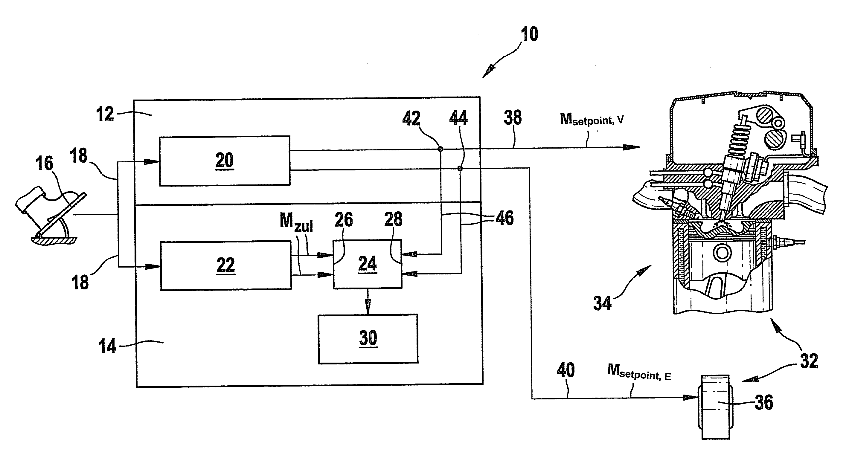
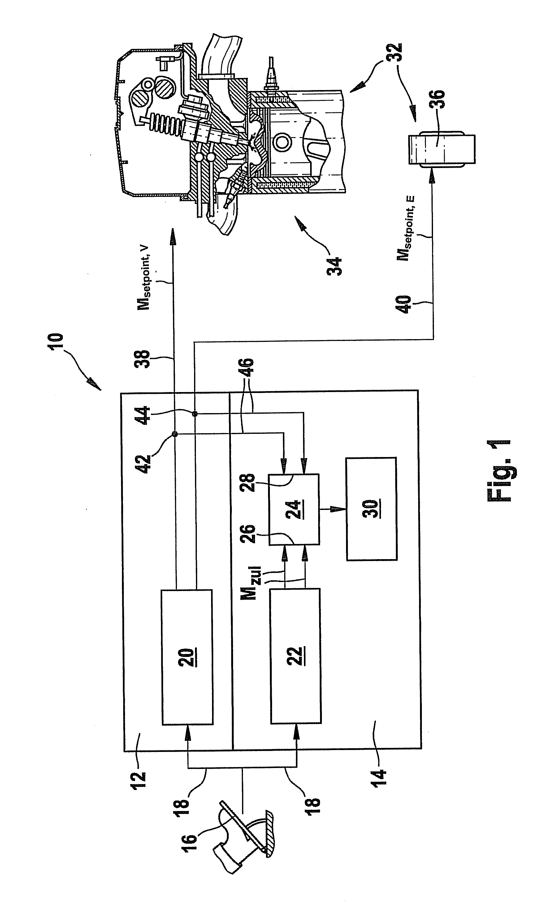
[0013]FIG. 1 shows continuous torque monitoring within a vehicle control unit, continuous torque monitoring being performed in a comparison stage between a permissible torque Mzul and setpoint torques Msetpoint,V and Msetpoint,E.

[0014]A vehicle control unit 10 shown in FIG. 1 includes a functional level 12 (first level) and a monitoring level 14 (second level). Both levels 12, 14 are integrated into the vehicle control unit 10. Depending on the position of a gas pedal 16 determined by the driver, which is used as the driver input transmission device, a setpoint value 18 of a setpoint torque is impressed on a calculation stage 20 provided in functional level 12 and also on a calculation stage 22 in monitoring level 14. In functional level 12, calculation stage 20 calculates both a setpoint torque Msetpoint,V 38 and a value for a setpoint torque Msetpoint,E 40. Setpoint torques Msetpoint,V 38 and Msetpoint,E 40 are output to a hybrid drive 32, which includes at least one internal comb...


PUM


Abstract

A method for controlling a vehicle drive unit, which comprises at least two individual drives, at least one of which is able to provide a negative torque. A vehicle control unit is provided, within which a continuous torque comparison is performed within a monitoring level. A permissible torque is ascertained therein. Using a torque range checker it is established whether ascertained setpoint torques lie within torque ranges of the at least two individual drives.

Description

FIELD OF THE INVENTION[0001]The present invention relates to a method for monitoring vehicles having multiple drives, at least one of the drives being able to generate a negative torque, thus, for example, a hybrid drive for hybrid vehicles.BACKGROUND INFORMATION[0002]A control unit for a drive unit is described in German Patent No. DE 103 20 016 A1, which in particular controls or regulates the drive unit in regard to an output drive torque, the drive unit being an internal combustion engine of a motor vehicle. The motor vehicle typically includes a driver input transmission device actuatable by the driver of the motor vehicle, in particular a gas pedal actuatable using the foot. This is provided to output an output signal representing an instantaneous actuation state of the driver input transmission device. A control unit receives the output signal from the driver input transmission device and assigns the received output signal at least one setpoint output variable, in particular ...

Claims


Application Information

Patent Timeline
Patent Type & Authority Applications(United States)
IPC IPC(8): G06F19/00B60W10/04B60W20/00
CPCB60L2240/423B60W10/06B60W10/08B60W20/00B60W50/045Y10T477/69368B60W2710/083Y02T10/6286Y02T10/642Y10T477/23Y10T74/19265B60W2710/0666Y02T10/64Y02T10/62B60W50/04B60K6/20
Inventor SEEL, ANDREASNIEMANN, HOLGERKAEFER, OLIVERHAGMAN, PER
Owner ROBERT BOSCH GMBH
Why Eureka
Try Eureka