NGL Recovery Methods and Configurations

a technology of ethane recovery and configuration, applied in the field of0002gas processing, can solve the problems of ethane recovery in excess of 90% that is neither achievable nor economically justified, and ethane recovery is often limited to 20% to 50%, so as to achieve desirable separation characteristics and increase power production

Active Publication Date: 2010-02-25
FLUOR TECH CORP
View PDF16 Cites 26 Cited by
  • Summary
  • Abstract
  • Description
  • Claims
  • Application Information

AI Technical Summary

Benefits of technology

[0010]The present invention is directed to configurations and methods of NGL production in which the temperature of the vapor feed to the demethanizer (most typically upstream of the turboexpander) increased by combining the vapor feed with a portion of unprocessed feed gas. Such configurations advantageously allow warmer operation of the demethanizer in the upper section, thereby eliminating carbon dioxide freezing under all operations, and further provide an increase in power production by the turboexpander. It should be especially noted that such configurations allow operation of the demethanizer with an optimized temperature gradient, which results in desirable separation characteristics despite higher temperature in the upper section.
[0011]In one aspect of the inventive subject matter, a plant includes a feed gas separator that is configured to separate a feed gas into a liquid portion and a vapor portion. A demethanizer is fluidly coupled to the separator and configured to receive the vapor portion and the liquid portion, and a turboexpander is configured to receive and expand at least part of the vapor portion in a location upstream of the demethanizer. In such plants, a feed gas bypass circuit is configured to provide part of the feed gas as a bypass gas to the vapor portion upstream of the demethanizer in an amount sufficient to prevent carbon dioxide freezing in the demethanizer.
[0015]Consequently, in a further aspect of the inventive subject matter, a method of separating a feed gas will include a step of providing a feed gas, and separating a first portion of the feed gas into a vapor portion and a liquid portion. In a further step, part of the vapor portion is expanded in a turboexpander, and the expanded part of the vapor portion is fed into a demethanizer. In yet another step, a second portion of the feed gas is combined with the vapor portion upstream of the demethanizer in an amount sufficient to reduce carbon dioxide freezing in the demethanizer.

Problems solved by technology

Such known configurations are commonly used for feed gas with relatively low CO2 (less than 2%) and relatively high C3+ (greater than 5%) content, and are generally not applicable for feed gas with high CO2 content (greater than 2%) and low C3+content (less than 2% and typically less than 1%).
Unfortunately, in most common configurations high ethane recovery in excess of 90% is neither achievable due to CO2 freezing in the demethanizer, nor economically justified due to the high capital cost of the compression equipment and energy costs.
Unfortunately, while high propane recovery can be achieved with such processes, ethane recovery is frequently limited to 20% to 50% due to CO2 freezing problems in the demethanizer when processing a high CO2 feed gas.
However, as in many high propane recovery configurations, the CO2 content in the top trays will increase due to the very low temperatures, which invariably causes significant internal recycle and accumulation of CO2.
Thus, such configurations typically result in high CO2 concentrations in the top trays, and are thus more prone to CO2 freezing, which presents a significant obstacle for continuous operation.
However, such CO2 removal option adds significant cost and energy consumption to the plants.
Such recycle schemes can also be used to reduce CO2 content in the NGL product to at least some degree, but deethanizer vapor recycling requires additional compression, heating, and cooling that often make such configurations economically less attractive.
However, all or almost all of them are relatively complex and often fail to achieve economic operation for high ethane recovery with high CO2 feed gases.

Method used


Image

  • NGL Recovery Methods and Configurations
  • NGL Recovery Methods and Configurations
  • NGL Recovery Methods and Configurations

Examples


Embodiment Construction

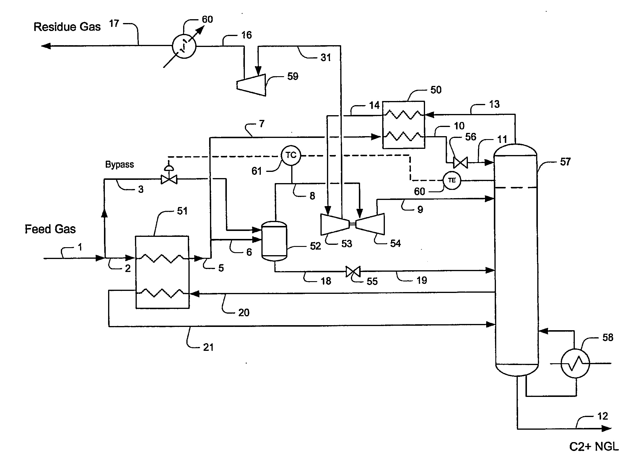
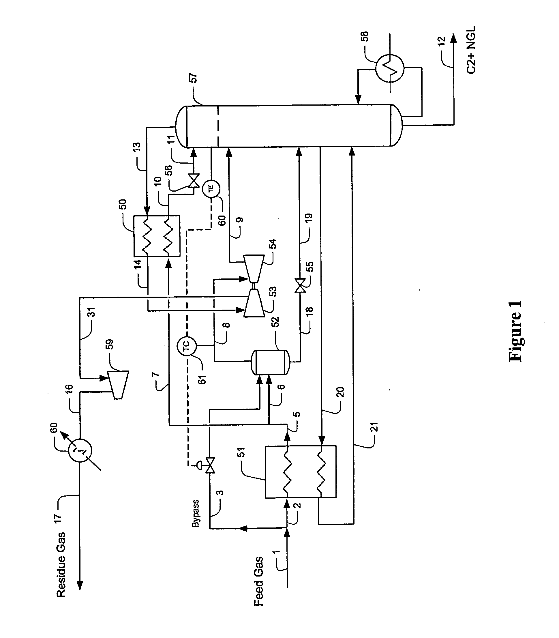
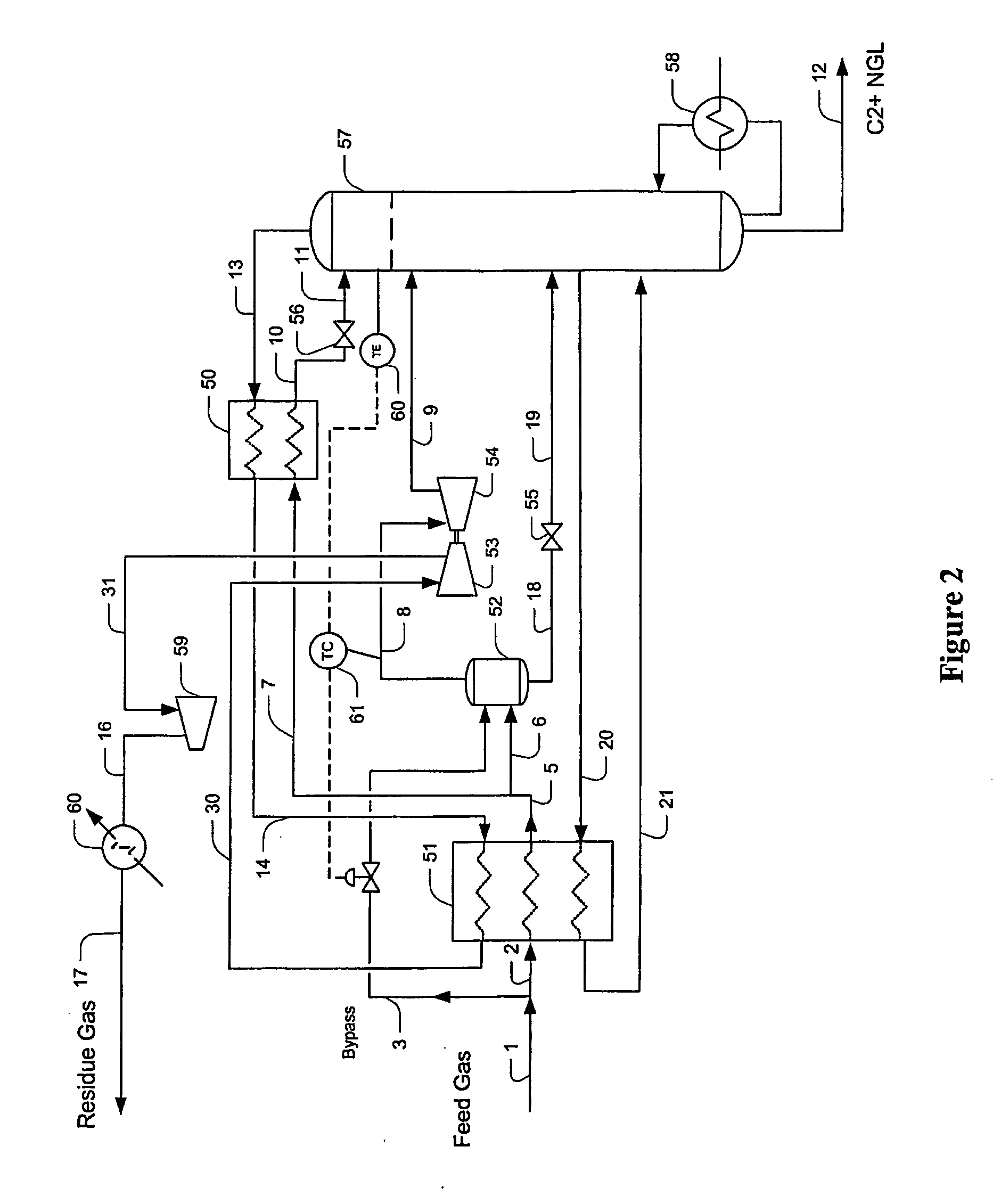
[0022]The inventors have discovered that high ethane and propane recovery (e.g., at least 70% to 90% C2, and at least 95% C3) can be achieved where an NGL plant includes a feed gas bypass that controls the inlet temperature to the turboexpander and / or the demethanizer to thereby strip CO2 content from the demethanizer bottom. Contemplated configurations and methods are particularly advantageous where the feed gas has a relatively high CO2 content (e.g., equal or greater than 2 mol %) as such configurations will also avoid CO2 freezing. Furthermore, such configurations and methods will advantageously reduce gas compression power requirement. Viewed from another perspective, it should be appreciated that the use of a feed gas bypass that is coupled to the demethanizer operation will allow stripping of CO2 from the NGL product to no more than 10 mol %, more typically no more than 6 mol % and most typically no more than 2 mol %, thereby reduce CO2 freezing, lower power consumption, and ...


PUM


Abstract

Contemplated NGL plants include a feed gas bypass circuit through which a portion of the feed gas is provided downstream to a vapor portion of the feed gas to thereby increase turbo expander inlet temperature and demethanizer temperature. Contemplated configurations are especially advantageous for feed gases with relatively high carbon dioxide content as they entirely avoid carbon dioxide freezing in the demethanizer, provide additional power production by the turboexpander, and recover C2+ components to levels of at least 80% while achieving a low carbon dioxide content in the NGL product.

Description

[0001]This application claims the benefit of our provisional patent application with the Ser. No. 60 / 702516, which was filed Jul. 25, 2005, and which is incorporated by reference herein.FIELD OF THE INVENTION[0002]Gas processing, and especially gas processing for ethane recovery / propane recovery.BACKGROUND OF THE INVENTION[0003]Numerous expansion processes are commonly used for hydrocarbon liquids recovery in the gas processing industry, and particularly in the recovery of ethane and propane from high pressure feed gas. Such expansion will provide at least in part for the refrigeration requirement in the hydrocarbon separation process. Additional propane refrigeration may be required where the feed gas pressure is low or where the feed gas contains significant quantity of propane and heavier components.[0004]For example, the feed gas in most known NGL expander plants is cooled and partially condensed by heat exchange with demethanizer overhead vapor, side reboilers, and / or external ...

Claims


Application Information

Patent Timeline
Patent Type & Authority Applications(United States)
IPC IPC(8): F25J3/00
CPCF25J3/0209F25J3/0233F25J3/0238F25J2200/02F25J2200/70F25J2280/02F25J2205/04F25J2210/06F25J2220/66F25J2240/02F25J2245/02F25J2200/76F25J2240/40F25J2215/60
Inventor MAK, JOHNNIELSEN, RICHARD B.GRAHAM, CURT
Owner FLUOR TECH CORP
Why Eureka
Try Eureka