Charged Particle Beam Lithography System and Target Positioning Device

Active Publication Date: 2010-02-25
ASML NETHERLANDS BV
View PDF28 Cites 10 Cited by
  • Summary
  • Abstract
  • Description
  • Claims
  • Application Information

AI Technical Summary

Benefits of technology

[0021]In an embodiment, the second actuator is arranged for reducing and/or minimizing of leakage magnetic and/or electric fields outside the second actuator, such as electromagnetic dispersion fields, at least when the second actuator is switched off.
[0022]In order to reduce the leakage of magnetic and/or electric fields, said second actuator may be provided with shielding means for at least partially shielding against leakage of magnetic and/or electric fields outside the second actuator.
[0023]Alternatively or additionally, in an embodiment the second actuator comprises an induction motor. In an embodiment the induction motor comprises a chore of non-ferromagnetic material. In an embodiment the non-ferromagnetic material compr

Problems solved by technology

For this new type of maskless lithography, appropriate stages have hardly been designed, at least are not commercially available.
Known stages, for as far as they can be adapted to maskless lithography, are mostly inappropriate at least in the sense of e.g. size, costs and vacuu

Method used


Image

  • Charged Particle Beam Lithography System and Target Positioning Device
  • Charged Particle Beam Lithography System and Target Positioning Device
  • Charged Particle Beam Lithography System and Target Positioning Device

Examples


Embodiment Construction

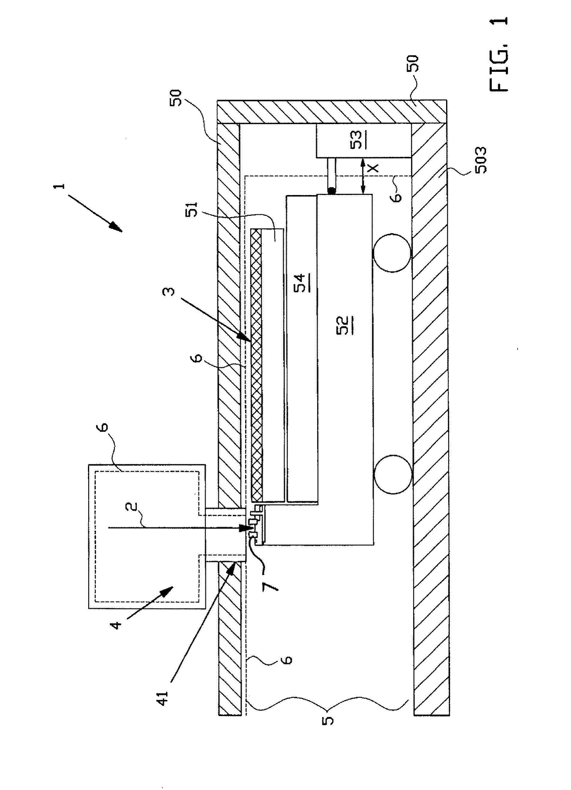
[0065]FIG. 1 schematically shows a system 1 for charged particle beam lithography, using a massive array of parallel charged particle beams, so called cp-beams. In the present example the charged particle beams are electron beams. One of such cp-beams 2 is represented in FIG. 1.

[0066]All cp-beams are controlled separately by means of a modulator in a known manner, enabling a writing of a desired pattern on a target 3, in this case a wafer. The main advantages of this system compared to the commonly used optical systems are the writing of very small structures and the absence of expensive masks. The latter significantly reduces the start-up costs of a batch, making the present system highly advantageous for prototyping and medium volume production.

[0067]The system according to the invention consists of three major subsystems, namely a data path subsystem (not shown in FIG. 1), a charged particle optical column 4, for example an electron-optical column, and a target positioning device...


PUM


Abstract

The invention relates to a charged particle beam lithography system comprising:
    • a charged particle optical column arranged in a vacuum chamber for projecting a charged particle beam onto a target, wherein the column comprises deflecting means for deflecting the charged particle beam in a deflection direction,
    • a target positioning device comprising a carrier for carrying the target, and a stage for carrying and moving the carrier along a first direction, wherein the first direction is different from the deflection direction, wherein the target positioning device comprises a first actuator for moving the stage in the first direction relative to the charged particle optical column,
    • wherein the carrier is displaceably arranged on the stage and wherein the target positioning device comprises retaining means for retaining the carrier with respect to the stage in a first relative position.

Description

BACKGROUND[0001]The present invention relates to a charged particle beam exposure system, such as a lithography system for maskless image projection, scanning and non-scanning electron microscopes, and the like.[0002]Charged particle beam lithography systems, such as electron beam maskless lithography systems, are generally known and, relative to conventional mask based lithography systems, have the advantage of fabrication on demand as it were, due to an absence of the necessity to change and install masks or reticles. In stead, the image to be projected for the manufacture of integrated circuits is stored in a memory of a computer that controls the maskless exposure system.[0003]The known charged particle beam exposure systems commonly comprise a charged particle column placed in a vacuum chamber. The charged particle column comprises a charged particle source including a charged particle extraction means and electrostatic lens structures for the purpose of focussing and deflectin...

Claims


Application Information

Patent Timeline
IPC IPC(8): G21K5/10H01J3/14
CPCH01J37/20H01J2237/20264H01J37/3174H01J2237/20292H01J2237/20278H01J37/3002H01J2237/2007H01J2237/202H01J2237/3175
Inventor PEIJSTER, JERRYDE BOER, GUIDO
Owner ASML NETHERLANDS BV
Why Eureka
Try Eureka